- Joined
- Dec 17, 2020
- Messages
- 56
There is no wiring diagram on either the South Bend Switch or the Dayton I took off.
Is there a way to test the thermal protection? Maybe resistance between P1 and P2 or?
I did separate all wires after I labeled and took notes of what went where.
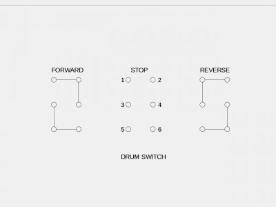
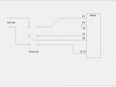
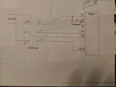
Someone on another forum gave me a diagram. I've been using it to figure out what's what.
I am sure now that the gray wire is P1 and the Pink is T2.
Testing T8 to black which looks like T5 is the Beep to OL (out of limits).
I hope this makes sense Thank you for your time mark.


