Group Project: Dividing Head - The Build

How about a semi hard material for the pin?

I turn a lot of 17-4 in h900 it’s around 43 hrc but still turns well and leaves a mirror finish
This is a good idea but I don't have that on hand. I may use 304 or 316. O1 is still an option if people this hardness is requisite. I am thinking that an harder pin would be less likely to jam in the tapered holes. I don't know if that is true?
 
This is a good idea but I don't have that on hand. I may use 304 or 316. O1 is still an option if people this hardness is requisite. I am thinking that an harder pin would be less likely to jam in the tapered holes. I don't know if that is true?

I have a lot of 3/4” diameter I can send you some if you can wait for it.

Will it come out of a 3/4” bar?
 
I have a lot of 3/4” diameter I can send you some if you can wait for it.

Will it come out of a 3/4” bar?
Thank you for the generous offer. I want to get this knocked out so I'm gonna make one out of 304. It will not be hard to replace the pin if that is inadequate.
 
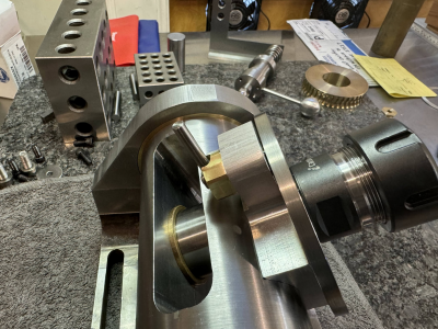
After much head scratching, here is my solution to the spring loaded index pin. So far it works very well!
Pin retracted:
1717981381660.png

Pin extended:
1717981601579.png

This is much easier to get a hold of and solves the clearance issues. The entire assembly with pin retracted is .588"
 

Attachments

  • 1717981416085.png
    1717981416085.png
    3.9 MB · Views: 4
Last edited:
I had the pin softer as it is cheap and easy to make and replace. Brass made it even easier to make. In reality, I doubt that any of use will use this enough to wear out anything. It is not like this is going into heavy commercial use.
 
  • Like
Reactions: rwm
Here is the subassembly:
IMG_4345.jpg

IMG_4347.jpg

This is a little finicky to get the pin length correct. Also it is not easy to screw the pin into the handle because there is no good way to grip it. I thought about slotting it but that would scratch the index. Ideally I could broach a hex in it but I don't have a broach small enough. Ideas?
That handle is two pieces of stainless that are silver soldered together. Came out well.
 
Last edited:
I had the pin softer as it is cheap and easy to make and replace. Brass made it even easier to make. In reality, I doubt that any of use will use this enough to wear out anything. It is not like this is going into heavy commercial use.
Totally agree. I am trying to use stainless or brass for the parts I would touch in use.
 
How about put the slot in the threaded end?
 
How about put the slot in the threaded end?
I had to put a center in that end so there is not a lot of meat there. It may be possible. Perhaps I could fill the center with silver solder and then slot it.
I also thought about making a micro-spanner and drilling two tiny holes in the taper end.

@Flyinfool - Your solution was the best. I slotted the back end. Works great! I'm calling it a win!
On to the spindle nut and worm mount. I do not have index plates so I am in no rush to make the sector arms and index pin. That's last.

Construction Note: Make the pin shaft .250 longer on the back end to allow for the center. Then, cut the center off after you have finished with that end. That leaves you solid material to slot for installation.
Duh :rolleyes: It's so much easier to see the future when you are in the future's past.
 
Last edited:
@Flyinfool - I think we might want to start a revision list on or offline.
I found some surprising behavior. If you clamp the spindle clamp and them tighten the two mounting screws that go into the trunnion, the spindle clamp will not un-clamp entirely! Those screws must hold it in a flexed position. My clamp is made to close tolerance and therefore is very sensitive. I think I would consider a redesign of the spindle clamp with only one larger mounting screw at the top, or move the two screws closer together. I suspect that the mount for the index pin is also moving slightly so using a single large screw at the top may minimize this. It would force the bottom of the clamp to flex more. I would also use counterbored holes to avoid the centering effect of a countersink. Machine screw countersinks are not very precise.
Also, if you want more clearance for the index pin assembly you could leave that design as is and use a thicker spindle clamp. If the clamp were 1" thick, you could machine that section down to .600 in thickness which would add at least .250 clearance.
You could add a lever to your existing knob? I think you are going to end up revising the bushing/knob assembly because the chamber for the spring is really small. Right now it is .544-.062=.482? Mine has at least .600 in length and I used a lighter spring and then cut it
I went with these bushings and they are perfect. My spindle has no slop at all.
The mounting hole in the trunnion would need to be enlarged to 1.750. The flats in the trunnion should be increased slightly in depth to .300 (instead of .250) to allow room for the bushing although this is not critical.
I had to drill a .250 hole in my index plate so I could access the spindle clamp mounting screws. I just rotate the spindle until the hole is over the screw. This really facilitates assembly and alignment of the clamp and is a nice added feature.
 
Last edited:
Back
Top