The Voron kit build thread

Keep an eye out for wear on the wiring in the cable chains.

Good eye!

I have been watching. I saw the two spots your (likely) noticing early on in the project. The X and Y both are like that, from the chains not laying flat. I have been keeping an eye on them.

While printing, the contact between the wire and the cable chain edge is static. It appears to be contact, but no rubbing, as the wires arent moving at all, just resting against the chain. I'm at 200 hours so far, and there's still no descernable damage to the wire insulation from rubbing.

I'll be keeping an eye on them anyway though.


This morning I spotted this handle design on printables. I bet it'll look great in Iron Red! I'm looking forward to seeing how they come out, printing with the Voron.

 
Last edited:
You should make those handles out of aluminum @Ken226. :grin:
 
Last edited:
How's it progressing. You guys making any headway?


I had the idea of moving my webcam the underside of the rear gantry rail. it looks like I can do it with my existing camera mount, and route the cable through the rear cable chain. It looks like it should clear everything, and has the benefit of staying level with the toolhead during prints.

See any reason I shouldn't do it, or anything i'm missing? If I move it to this spot, i should be able to redesign my front center caselight bar to a solid, one piece design.

Something like this:

RearMount2.jpg
 
I think having it move with the gantry like that would be great!

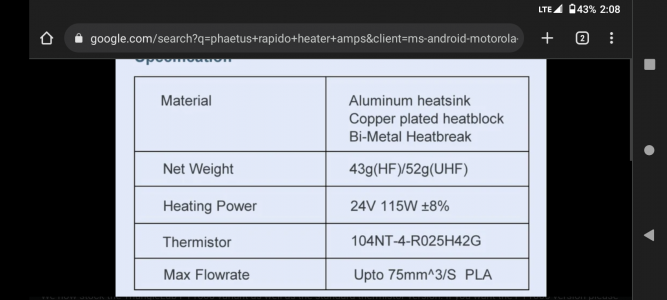
As far as my build is going, it is coming along slowly. I am currently wiring it, and dealing with the cable chains is a real PITA. I also have a bit of analysis paralysis going on regarding the electronics and the wiring. I want to do it correctly, and since I am using the Phaetus Rapido hot end, I have a couple of forks in the road. Due to the initial high current draw during startup, it has been advised to utilize the bed heater output on the Octopus instead of the normal hot-end output, which will require heavier wire than what would normally run to the PCB. So then I ask... Should I run separate wires up to the two-piece tool head into the 12-pin Molex or bypass PCB entirely? Will the PCB handle the current draw? It seems that it should but...
I was in the process of installing Tap, but the short linear rail and carriage seemed to have an issue with it not being smooth in operation. The vendor sent me another one that he checked out, although it did not seem much better than the first one. I am also short on Molex Micro-Fit 3.0 crimp terminals. I did purchase what seems to be a very nicely functioning crimper for the crimp terminals, so that was a plus!

Oh, one more thing. The wife has "mentioned" a few times that our laundry room is not done. :rolleyes:

My PCB is the one piece, but is likely similar. It showed a 50 watt limit for the heater circuit in the documentation.

At 24 volts, 50 watts will draw 2 amps of current.

I tried a Google search to see what the power output of the Phaetus Rapido is, but didn't have any luck.


You could bypass the PCB and use whatever power output the octopus or wiring allow, or you can use the PCB and limit the power in the configuration.

Go into the printer.cfg file and reduce the max output to the heater, to a percentage that won't exceed the pcb's 50 watt limit.


Right now, my v6 has a 65watt heater, but I've set the max output in the printer.cfg file to 76%, which should keep it below 50 watts. It's been running great.

You'll do the same with the bed heater anyway. The startup/setup guide had me do a similar limit based on the size of the Voron heat bed. Mine bed heater is set to 65% max, to prevent warping.
 
Somewhere, buried amongst the hundreds of posts and forums regarding the Voron build, is a comment or document that said the startup current draw was slightly over 100 watts. The chance of me finding that source again is pretty much zero.

I am going to run separate wires to the heater thus eliminating any potential issues.
 
According to West3D, it's 115 watts at just over 4 amps.

The PCB definitely wouldn't like that!
 

Attachments

  • Screenshot_20230115-140830.png
    Screenshot_20230115-140830.png
    269.7 KB · Views: 97
Back
Top