Risers.

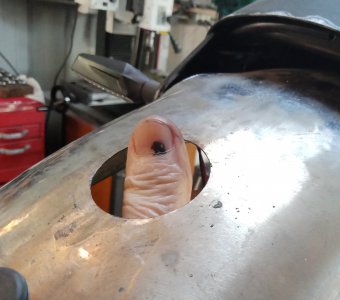
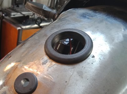
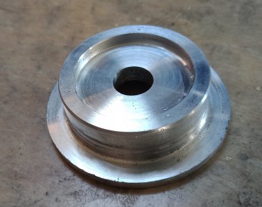
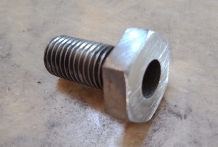
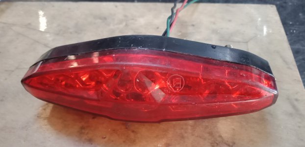
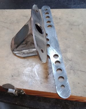
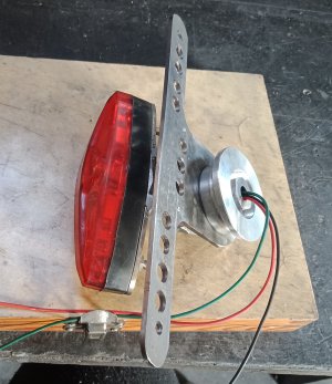
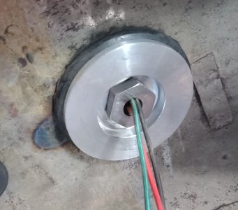
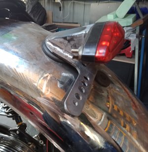
Some work on the rear end: The guard was badly dented and had a couple of cracks running out from the tail light fixing holes. I cut the lip from the periphery off, removed some dents as best I could and removed the bracing underneath at the rear end of the guard. The cracks I removed by drilling a bloody great hole, around 48mm, in the mounting area. This left a bit of problem on how to mount the new tail light. The solution was to insert a big grommet in the hole with a 38mm ID hole, next I spun up an aluminium bush to fit inside the grommet with a 50mm lip to compress the grommet. The tail light base was fashioned from 3mm steel with a 10mm nut welded in the middle. Over that I welded a bit of 30mm square tube and welded a flat plate on the other end the same shape as the tail light. Next I mounted the bracket on the mill and drilled some lightning holes. A 10mm fixing bolt was drilled through for cabling access to the light. I was worried about the tail light twisting in the grommet there being just one bolt securing it, but when done up, it proved to be solid as. Off to buy some paint this afternoon, so tomorrow I'll prep everything for paint and lay down some gloss black.
 

Attachments

  • a.jpg
    a.jpg
    615.7 KB · Views: 8
  • b.jpg
    b.jpg
    778 KB · Views: 5
  • c.jpg
    c.jpg
    937.3 KB · Views: 4
  • d.jpg
    d.jpg
    583.8 KB · Views: 4
  • e.jpg
    e.jpg
    916.9 KB · Views: 4
  • f.jpg
    f.jpg
    1 MB · Views: 4
  • g.jpg
    g.jpg
    1.1 MB · Views: 4
  • h.jpg
    h.jpg
    573.9 KB · Views: 5
  • i.jpg
    i.jpg
    1.1 MB · Views: 5
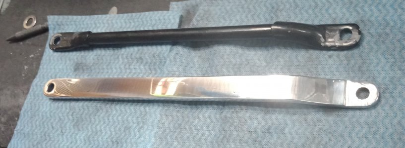
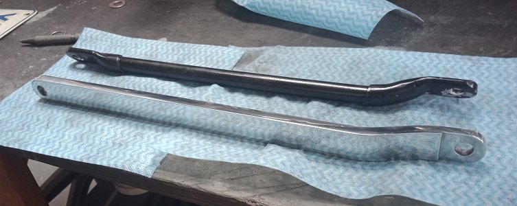
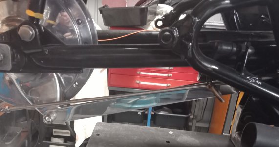
A nice new brake anchor made up today. Looks better than the old crusty steel one. Made from a slab of 10mm aluminium, cranked 12 mm and shaved down to 7mm on the leading edge.
 

Attachments

  • IMG20210508145522.jpg
    IMG20210508145522.jpg
    640.8 KB · Views: 4
  • IMG20210508145553.jpg
    IMG20210508145553.jpg
    916.7 KB · Views: 5
  • IMG20210508145642.jpg
    IMG20210508145642.jpg
    703.1 KB · Views: 5
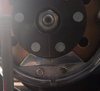
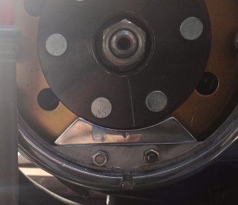
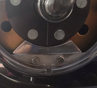
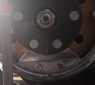
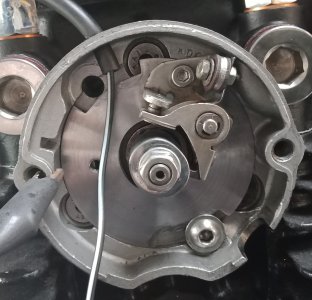
Today I messed around with the single points cam I made a while back. As you can see in the first two pictures the lobes were slightly off: when the right hand cylinder was timed correctly the left was slightly advanced, not a great deal, split the difference and have the right a smidgin retarded and the left a smidgin advance and it would run fine, But just to satisfy myself, I decided to see how close I could get them, after all I'm working with minute measurements here, so pulled out the files. As it happened, I managed to get them spot on, statically timed anyway, with very little work. The problem now is the keyway is slightly off, so the points backing plate has to be turned fully clockwise in order the get the timing right. So, now I know it is possible to get the lobes right, harder though is the keyway: I turned the cam around and set the backing plate midway, with the cam running free (no key) on the advance shaft, I turned the cam by finger and and marked where the keyway should be cut, unfortunately, you only halve to be a smidgin out to ruin it, and you guessed it, I was that smidgin out. So, tomorrow I'll make another cam, but this time I'll try cutting the keyway first and then filing the ramps. Fingers crossed. BTW, this was the problem with the commercially available cams, the lobes weren't set 180 degrees apart, making timing difficult. Many of the XS650 shops don't stock them anymore for this reason.
 

Attachments

  • IMG20210510101548.jpg
    IMG20210510101548.jpg
    646.2 KB · Views: 2
  • IMG20210510101811.jpg
    IMG20210510101811.jpg
    646.4 KB · Views: 3
  • IMG20210510102719.jpg
    IMG20210510102719.jpg
    410.5 KB · Views: 3
  • IMG20210510101548.jpg
    IMG20210510101548.jpg
    646.2 KB · Views: 3
  • IMG20210510105124.jpg
    IMG20210510105124.jpg
    651.9 KB · Views: 3
Doesn't look like anyone on this platform is interested in bike builds, so this will be my last post here.
 
I check in on your posts, good work being done :encourage:
 
Back
Top