Good Morning,
My Enco 12 x 36 Model 510-2584 (110V single phase) is having some issues and I'm not real sure what to do. Here is some background
1. It would not go in reverse, I took the switch apart, one of the indents was broken and the broken piece and spring (it has 4) was preventing it from physically rotating, I removed the broken piece and reassembled. I made a diagram of the wiring before I took it apart and about 95% sure it went back together the same way. It now will for in the forward and reverse rotation.
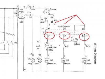
2. The power start switch has been broken for about a month, the knob fell off of it, It is just a 4 post switch (2 wires for the Power Start, 2 wires for the indicator light) I had just been physically jumping across the two power start post (I know its not the right thing, but it allowed me to use it until I got a replacement).
Now that I've taken the forward/reverse switch apart, the Power Start will no longer energize the contactor, you have to manually push the little square button on the contactor. Once that is done, everything works fine, it goes into forward/reverse, Emergency Stop works, Inching Works, and Power Light illuminates.
Does the forward/reverse switch circuit into the Power Start switch? How does the Power Start energize the contactor? (by that I mean, does it do it by completing a electrical circuit, or a ground circuit?) Other than checking for resistance to see if there are breaks in wires, how would I test the Power Start circuit? if there is actual power that runs through it when the circuit is completed, how do I test for it and what kind of voltage am I looking for? One of the poles on the Emergency Stop switch, the wire (a red wire) is split and also runs into the Power Feed, Im assuming this is the power feed since its common? When testing for voltage on a system like this, how do you do that? Do you put a positive lead from your multi meter on the wire, and the black on a grounded piece of the lathe? I apologize, my electrical knowledge is very very basic, I can normally manage to work my way through things, just need some help with understanding some of the basics.
v/r
Thomas


