Tool Post Grinder -Making a new one...

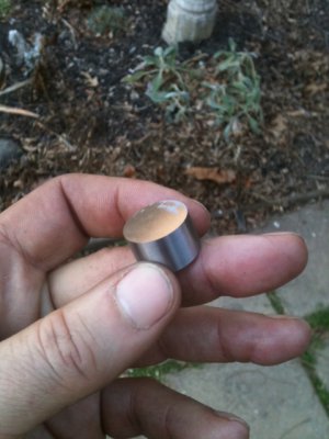
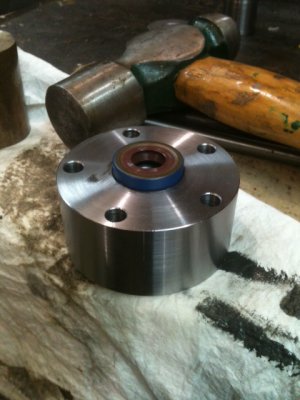
So, here's the metal. I wanted to take a test cut and check the hardness and if you look in the center of the small surface ground piece in my fingers, you can see the impact divots from the Brinnell tester. Mine has a round ball impacter on it right now. And the results are RC 40 tested at the center and inside section of that cut . If I test at the outside end of that cut piece (which is 1/2" long), its RC 43. This is because the ends of the rod cool off faster during the quench.

Anyhow, the goal was 42 and we got 40... Close enough to go puff on a cigar for a while...

Z2.JPGZ1.JPG


... And one other thing... I appreciate the kind words and sentiment but, the term "Machinist" should be reserved for those who supported themselves and made a livelihood doing it; nor, am I a Craftsman. I don't have an artistic bone in my body. In general, "Advanced Hobbyist" is fitting and appropriate...

Ray

Z1.JPG Z2.JPG
 
... And one other thing... I appreciate the kind words and sentiment but, the term "Machinist" should be reserved for those who supported themselves and made a livelihood doing it; nor, am I a Craftsman. I don't have an artistic bone in my body. In general, "Advanced Hobbyist" is fitting and appropriate...

Ray

all right all right, Master Advanced Hobbyist it is then :) Besides art and science are just two sides of the same coin, a perfectly turned piece is just as artful as a bucket of paint splashed on a canvas.
 
Well, this was easy; took about an hour (because I'm in slow-motion mode these days) and the best part is that it only took one try.


So here's how things go...

First, I have absolute faith in my 5C collet chuck and I know with great certainty my tailstock is dead on. -These things are pre-conditions -always! If you don't know and trust your machines, work at it until you do.

I started out by selecting the 15/16 collet sticking the shaft all the way in with just an inch sticking out. -Face it, drill a center hole then, turn about 1/2" of the side down to 3/4" dia. Flip the shaft around and do the other side. Now, grab a 3/4" collet, insert one of the fresh ends, tighten things up and put the live center into position on the tail end. None of this is shown in pictures BTW.


I'm using carbide so, this piece being under 1" and ultimately going down to 1/2" needs to spin between 1400 and 1800 RPMs.

First, I'm going to work from the inside out. BTW: Initially, I wanted the largest diameter in the center to be 1.1" dia but, the closest piece of stock was 15/16". -No big deal because that large diameter only needs to be big enough to push against the thrust washer.

First, I take a pass about 10 thou DoC just to get the scale off. Important: Set your crossfeed dial to zero as a reference point and as you're doing this, never lose track of where the dial was set from the last cut.

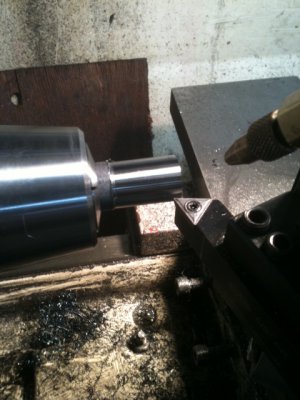
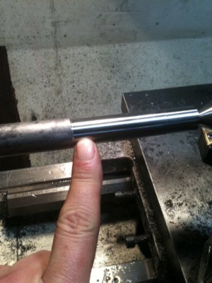
The area I'm pointing to is where the taper bearing will be pressed onto. It's critical dimension that needs to be 1 thou over the bearing ID. The diameter needed here is between 0.6875 and 0.6885 (because the bearing ID is 0.6875). I want a slight sweat interference fit.
P2.JPG

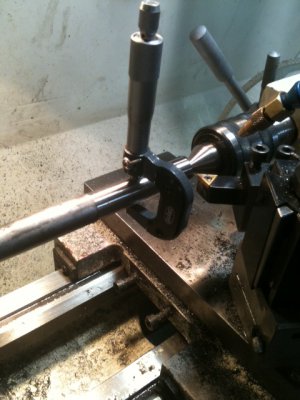
Next, take three critical measurements (left, center, right) of the area you just cut. If you have taper, now's the time to fix the tailstock. And if you don't trust your chuck, spinning between centers is probably a better alternative. In this case, the taper over that 3" segment was about 0.0001" -good enough!
P1.JPG

My first measurement here was 0.8835". Now, dial in exactly 10 thou and take another pass. I'm going to make successive passes at 10 thou because with metal this hard it's the lightest cut you can take and still get a good finish. Deeper cuts will bend a shaft this long and thin. Second measurement was 0.8645" so the difference is 19 thou. Dial in 10 more, take a pass and measure. Next one was 0.8450" for a difference of 19.5 thou. This process continues and after several more cuts, it's clear that every time I dial in 10 thou, about 19.5 thou comes off the diameter.

With a starting diameter of .8835 and a final diameter of .6885, I'll need to make about 10 passes. The trick is to carefully watch and adjust your settings so your last pass is taken at about 10 thou DoC. You don't want to take your last pass at 15 thou DoC because that might bend the rod and not take off the 30 thou you were hoping for.

Also, sometimes you'll get intermediate readings like .7693. The dial only has 1 thou graduations so, the next cut you take, split the numbers as best you can.

Heat: I was running mist coolant for the whole job and I could tell the part was about 100 to 110F. Even this slight amount will expand the piece very slightly. Let's say your final cut need to have 19.5 come off. Theoretically, you should dial in 9.75 thou more from your last cut. In a case like this, the part will decrease about 0.0001 when it cools off to 68F. I would make every attempt to read the dial and increase by 9.7 thou (you need to estimate between the lines).

As it turns out, on the last pass of this, the mic read 0.8683. The part has now cooled to room temperature and it's reading exactly 0.8682. I was hoping for 0.8685 so I'm 3 tenths shy but, still within spec of my desired -0.0000, +0.0010 tolerance from 0.8675.
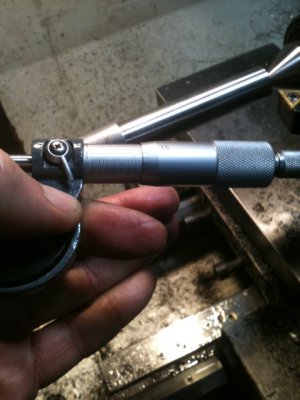
P3.JPG

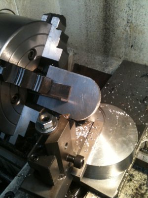
And here's what the finished piece looks like. The 1/2" diameter area, now that it's room temperature is reading 0.5006 (within spec). The intermediate diameter is 0.6252. It was supposed to be 0.6250 (in spec).
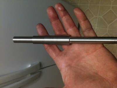
P4.JPG

And finally, Senna is right. The proper way to do this is with a cylindrical grinder or a TPG -but you can get real close to perfect with a lathe.


Ray

P1.JPG P2.JPG P3.JPG P4.JPG
 
Ray--thanks for sharing the reasoning and details of all this with us. Just curious if you had checked the bearing ID, yourself, prior to fabricating the shaft?
 
Thanks...

Yes, absolutely I checked the bearing ID and OD. The taper bearing was an expensive, precision bearing that was one of a matched set. Picked it up for 50 bucks (normally 250 for the set). The specs said 0.6875 and that's exactly what I read using a telescoping gauge at indoor room temperature. It read about a tenth less in the garage where it's much cooler.

I didn't cut some of the body sections until the radial and thrust bearing arrived as I wanted to verify them before cutting metal. They too were dead on as advertised. I did however cut the cavities for the wave spring washers but, the tolerances there are loose as a goose.


BTW: This metal shaft did indeed harden all the way through. From the first cut to the last one, the machine never changed pitch as it does with uneven metal as you cut deeper. In this case, every cut sounded and felt the same. I don't think I'll need to re-make the shaft. It's plenty hard and was sparking a good bit as hard metal tends to do.


Ray


Ray--thanks for sharing the reasoning and details of all this with us. Just curious if you had checked the bearing ID, yourself, prior to fabricating the shaft?
 
Just a little more work today... Fun work -and the welding went a little better on the thicker aluminum. Just a couple more pieces to make; namely, the bottom bracket and sheaves. Still waiting on the wave spring washers and oil seals which are supposed to arrive around Jan 3.

R1.JPG

Yep, you're thinking the same thing I thought... -Looks kind'a like a toilet paper hanger :). See, I told you; I don't have an artistic bone in my body.

R2.JPG

Ray

R1.JPG R2.JPG
 
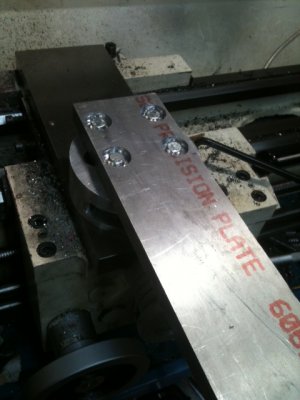
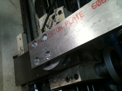
Still dilly-dallying along here, working on the bracket. I didn't pre-design this part as it's my experience that when it comes to matters of "ergonomics" and basic positioning, setting-up prototypes is very productive. In this case, I fiddled around with a few methods of making the bracket to find a solution that was simple and effective. Here's what we have so far. I'm re-using the base to the ball turner simply by drilling some holes in it. It can still be used for the ball turner. Also, you might be wondering why I'm using aluminum... To be honest, I'm not all that crazy about AL but it happens to be very good at damping vibration and if thick enough, is pretty darn strong.

It attaches to the crossfeed like this:

X1.JPG

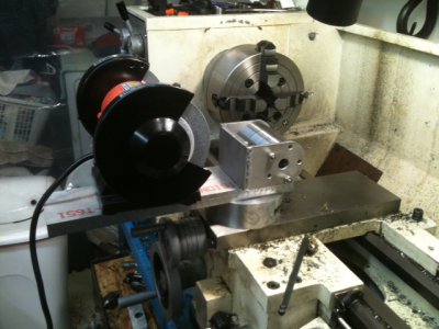
Here it is with the components laid roughly in place. BTW: I bought the little HF grinder just for the motor to drive the TPG. I'll remove the grinding wheels and covers and put a sheave on one side. As for the TPG, depending if a 4 or 5" diameter wheel is installed, there's enough crossfeed travel to work on very small diameter shafts up to 5.5" diameter. That should be more than adequate for my needs. Anyhow, everything has clearance with the head and tailstock.


X2.JPG


Ray

PS: I have no idea why this additional picture insists on being inserted in this post. -Go figure...

X1.JPG X2.JPG X1.JPG
 
Slowly, the parts are arriving... The thrust washers arrived today. All that's missing now is one of the oil seals. -Bummer... I ordered two seals from the same place at the same time and they shipped them separately. -Go figure.

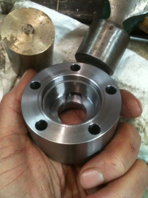
Everything is fitting nicely so far. By warming up the cap and cooling the bearing race, it fit in the recess with a few light taps with a brass rod. Same story when fitting the shaft in the OD of the bearing.

Y1.JPGY2.JPG

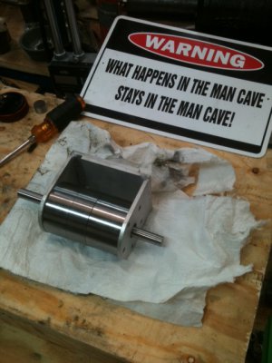
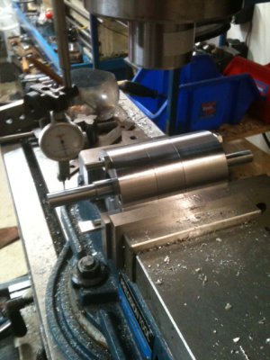
So, here it is partially assembled and being tested for runout. That's a Tenths TDI and it's rock solid. The needle sits on one line and just twitches a bit... Cool...

Y3.JPG

One little bit of bad news though... The little HF grinder that was purchased just to use the motor is totally inadequate and has no power whatsoever. I'll return it. By pressing my thumb on the smooth part of the shaft, I could lock-up the motor.

I have a 3 phase, 1/3 HP motor that I could use but, it's ultra-industrial duty and weighs WAY too much. Seriously, the thing is about 45+ lbs and I just don't want that much weight sitting on my carriage and way nor do I want to heave it up there every time I use it. -The search for a motor continues...

BTW: The rest of the bottom bracket is all done but, I was in a hurry and didn't take pics. -We'll catch it next time.


Ray

Y1.JPG Y2.JPG Y3.JPG
 
Ray, have you considered using a DC treadmill motor and control?

I'm thinking you could select pulleys to maximize torque and use the speed control to find the best rpm to give you the best results.

They aren't too heavy either.

Just a thought.
 
All possibilities are on the table and I'm open to suggestions... This time of year, everyone is making New Years resolutions to lose weight so, in a few months, all the unused treadmills will become available :).

Good thought... I don't plan to weld any of the motor brackets so, I can change things later as desired.


Ray


Ray, have you considered using a DC treadmill motor and control?

I'm thinking you could select pulleys to maximize torque and use the speed control to find the best rpm to give you the best results.

They aren't too heavy either.

Just a thought.
 
Back
Top