Tool Post Grinder -Making a new one...

Ray C

Registered
Registered
Joined
Nov 16, 2012
Messages
5,596
I've decided to re-make my tool post grinder. The one I had was also home made but the bearings were a special design and the housing was too big. Today, I drew-up the plans for a new one using commercial bearings. The front bearing is a high precision Nachi-Fujikosi that was NIB that I picked-up for $50 (normally about $250). It's a roller/taper type that can handle radial and axial loads. The rear bearings are a standard needle-nose thrust and a needle-nose radial. The PDF should show the whole picture pretty clearly but, I did not include the wavy pressure spring that keeps the shaft and taper bearing under load. This thing will be sealed and filled 1/2 way with ATF. BTW, does anyone know of a source for 1/2" diameter grease or oil rings? Right now, the diagram shows O-ring grooves but, I sure would like to use seals instead.

I'll start building this thing soon but, can't do some of it because the thrust and radial bearing haven't arrived.


Ray

PS: Click the PDF file and you can rotate the image in 3 dimensions.

View attachment TPGAssembly.pdf
 
Look for a CR (Chicago Rawhide I believe) distributor. If they don't have the seals you want, they probably don't exist.
 
Last edited:
I've decided to re-make my tool post grinder. The one I had was also home made but the bearings were a special design and the housing was too big. Today, I drew-up the plans for a new one using commercial bearings. The front bearing is a high precision Nachi-Fujikosi that was NIB that I picked-up for $50 (normally about $250). It's a roller/taper type that can handle radial and axial loads. The rear bearings are a standard needle-nose thrust and a needle-nose radial. The PDF should show the whole picture pretty clearly but, I did not include the wavy pressure spring that keeps the shaft and taper bearing under load. This thing will be sealed and filled 1/2 way with ATF. BTW, does anyone know of a source for 1/2" diameter grease or oil rings? Right now, the diagram shows O-ring grooves but, I sure would like to use seals instead. I'll start building this thing soon but, can't do some of it because the thrust and radial bearing haven't arrived.
Why ATF (and which one?) I would have used transhydraulic oil.
 
Why ATF (and which one?) I would have used transhydraulic oil.

ATF... For the most part, it's just a lightweight hydraulic oil (about 7 to 10 W) dyed red. In modern transmissions, it makes a big difference of course but, for chrome steel bearings, nothing fancy is needed. I have countless gallons of hydraulic oil in storage but, it's all too heavy for a 1/3HP motor.

Anyhow, I think I have some fresh Dexron type from the last time I bought a bunch for heat treating. According to the CAD calculations, this will only need 1/2 ounce.

Marcel and Tony: Thanks for the tips... I'll see if I can locate those seals. I looked for about 30 minutes and couldn't find a place that sold 1/2" ID.

EDIT: BTW, the bearings are rated for insanely fast speed (upward of 15k RPM) but I'm only planning to let this thing top-out at 5k RPM. The motor is a 1/3 HP 3 phase that I drive with a VFD.

Ray
 
Last edited:
Someone asked for a better view so, here it is. The wavy pressure washer will go to the right of the green thrust bearing. The thrust bearing is shown as a monolithic piece when in reality, it's 3 pieces (2 disks sandwiching a plate with rollers). The purpose of the pressure washer is to constantly apply force against the thrust bearing and in-turn, the shaft which in turn presses the taper cone into the taper race. I want the pressure to be upward of 150-200 lbs. The thrust bearing can take 5000lbs (dynamic) and taper bearing can handle an insanely high force.

The taper bearing race fit will be 1 tenth interference (i.e. sweated in). The needle radial will be a zero tolerance fit.


Ray

View attachment TPG-Exp-Assembly.pdf
 
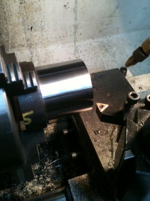
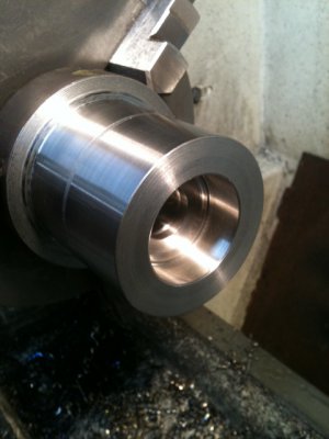
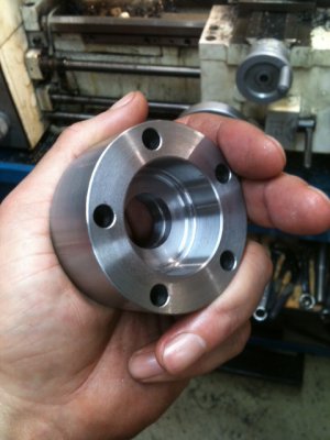
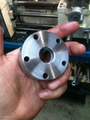
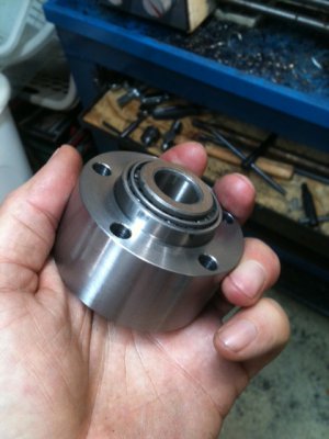
Ok, here's some action shots... This is the front cap that holds the taper bearing.

This metal is 1045 that I fully annealed then, heat treated so the inside of the stock should be about 35 RC. That should be plenty hard for this application. Normally, folks will anneal then machine then, heat treat then, re-machine to size. In this case, 35 RC is not hard to work with so, I'll just work with slightly hardened metal. I actually prefer that as it cuts nicer.

The bore diameter for the bearing race is cut 1/2 thou under size of the race (which happens to be 1.571"). In the last pic, you can see it's a nice fit. The rounded edge of the bearing fits in then it stops. If I warm the cap to about 200F and cool the race in the freezer, it will drop right in.

The through holes were done on the mill using the DRO to put them 72[SUP]o[/SUP] apart for a standard 5 bolt pattern.

Enjoy...


C1.JPGC2.JPGC3.JPGC4.JPGC5.JPG

Ray

C1.JPG C2.JPG C3.JPG C4.JPG C5.JPG
 
Ray, you using a LH tool to cut RH, or did you feed out....or are you using this to face?

Looking good so far!
 
It was a side cut going from right to left but every now and then, I'll use a LH tool and reposition the QCTP so the engagement angle is still correct. Often times I'll do this depending on what inserts are loaded-up. In this case, to get that finish, I wanted a wider radius and that was the most convenient bit at the time. -Yes, I know, there are dangers in doing this...

I used a naked carbide RH tool to get most of the meat off and it was on it's last leg when I started. I used it until T minus 70 thou, switched over to that fresh bit, took a first cut, gauged it out and lined-up for the kill. Missed the mark on the OD by a thou but, it's far from critical.

BTW, I'm loving these new boring bars I picked-up not long ago. I'll show a pic. Flat insert with no breaker. Man, they work great.

Ray


Ray, you using a LH tool to cut RH, or did you feed out....or are you using this to face?

Looking good so far!
 
Just a thought, but have you considered putting a couple of holes through for bearing race removal?
 
Back
Top