Tool Post Grinder -Making a new one...

Hmmm, let me see if I can post a JPG. The files I'm posting are 3D PDF format and maybe your computer doesn't like it. Stand by...

Ray


Sorry Ray, been busy with the Tool and Cutter Grinder, I missed the start of this. Looking good so far. When I open the files all I get is a white page with the title at the top?? Any ideas ??

"Billy G"

- - - Updated - - -

Try this, Bill. It's just a picture file.
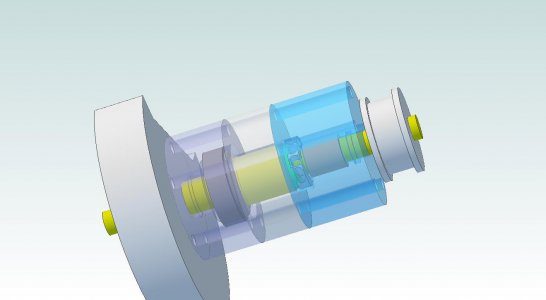

TPGAssembly.jpg

Ray


Sorry Ray, been busy with the Tool and Cutter Grinder, I missed the start of this. Looking good so far. When I open the files all I get is a white page with the title at the top?? Any ideas ??

"Billy G"

TPGAssembly.jpg
 
Thank you Ray. I see that one. I never had trouble with any type PDF before?

"Billy G"
 
Oh yes, it's a concern... I finally did get around to finding some grease/oil seals just like the ones you pointed to. A dealer on Amazon is where I'll probably get them but haven't selected the precise ones yet. Anyhow, as temperature changes, it will expand the fluids and/or slight pressure will build up... If needed, I could put a small vent in there.

Do realize folks, I designed this thing "off the top of my head". The front main bearing is probably way too big for the application but, it's what I happen to have on-hand because I picked up a precision bearing on eBay for cheap -so I'll use it. I should also spend a few more moments calculating the correct pressure to be generated by the wavy-washer. -Needs enough pressure to keep the taper bearing seated and not too much pressure to be a burden. It may take a little trial and error.... The bearings are capable of WAY more RPM and force than this application calls for but as mentioned, this whole thing is made from shop drops (with the exception of the rear bearings which cost a whopping 20 bucks).

Hang in there with me on this project... BTW: I have a good bit of time off these days so, I should make steady progress building it. -Still waiting for the rear bearings though and I can't finalize the drawings until they arrive.

Ray


Perhaps this is the way things are normally done. Is there any concern about cavitation causing blown seals? Maybe try McMaster-Carr for lip seals. http://www.mcmaster.com/#ring-seals/=pxxf8y
 
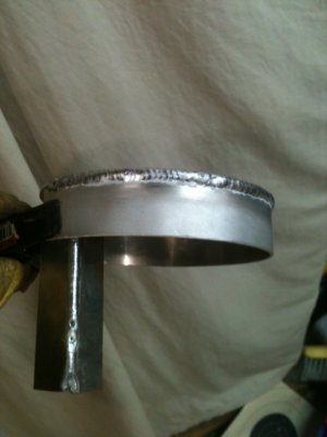
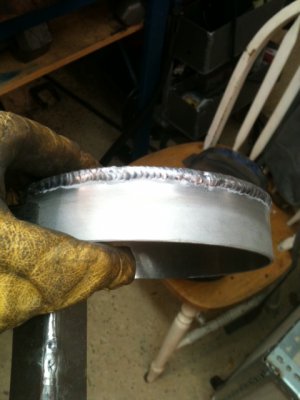
Oh boy, almost ashamed to show these. It was a bit of a white-knuckle ride. If you look closely, you can see the personality of about 6 different amateur welders -which is about how many times I had to start n stop this thing to make it all the way around. If anything, the weld is sunk well and is very solid. This is 6061 plate aluminum, 1/10" thick. I was running about 65 Amps and could only go about 1.5 inches because it heats up so fast. There's only a couple small voids which I won't bother to chase after.

Goes to show... "use it or lose it". Last year when I was doing a lot of AL TIG, this would have been a snap and looked much better.

EDIT: BTW, that piece of scrap clamped to the lip is not a part of this. It was just a heat sink at the very end of the round band. -Necessary to prevent the last 1" from melting before your eyes...


G2.JPGG3.JPG

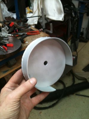
At least there were no burn-thru's or bottom-side bellies. On the up-side though, it looks good after a quick sandblasting. All ready for some paint (to obfuscate the bad welding).

I'll mark-out the cut-aways, put it in the mill and be done with this piece soon.

G4.JPG

Ray

G2.JPG G3.JPG G4.JPG
 
Last edited:
I have a cast guard from a Dumore if I build a grinder. It appears to be a little smaller than yours, but no welding required. Yours looks fine. I probably would have just fused it on the outside and put a nice fillet inside. That way I could put a radius on the outside edge and not hurt the strength, and no one would see my ugly weld.

Or if I were just lazy, I'd machine it out of solid.
 
That would have been a lead pipe cinch out of a billet. Tough getting a good bead on thin material. Good job though.

"Billy G"
 
@Tony: This plate a little large because of the way I intend to affix the front safety plate. You'll see that soon enough. Anyhow, I'm only planning to use 4" wheels on this but, it will accommodate a 5" (in case I ever need to grind a very small diameter shaft).

@Bill: Aluminum is just plain finicky -especially thin. I was really dreading the torch work on this because I knew I was out of practice. I thought of making it from steel because it's a million times easier to weld. Problem was that all the sheet pieces laying around are too big and didn't want to chop it up just for a 6" square piece....


.... I know that Santa exists so, maybe I wasn't a good boy this year and got passed up. The bearings have not arrived for this project so there will be no Tool Post Grinder under the Christmas tree this year...


Ray
 
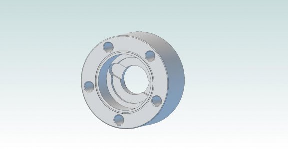
Ok, after some thought and a suggestion from Tony, here's how we'll address the removing the bearing race. We'll carve a couple slots to facilitate a puller. I'll probably need to make a special puller (some day) but, that won't be a difficult task. This method was chosen since A) the bearing will probably last a very long time and B) the other option of drilling thru-holes didn't appeal to me because, the holes would need to be very small diameter (about #8-32 screw) and be threaded all the way through -about 1/2". Also, the thru hole would be very close to the edge of grease seal on the other side.

Also, as per plan, I've included a small round groove on the face to either accommodate an O-ring gasket or (more likely) some liquid Permatex.

So, here's what it looks like now.

TPGTaperBearingCap.jpg


Ray

TPGTaperBearingCap.jpg
 
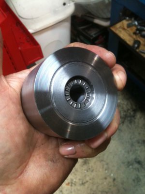
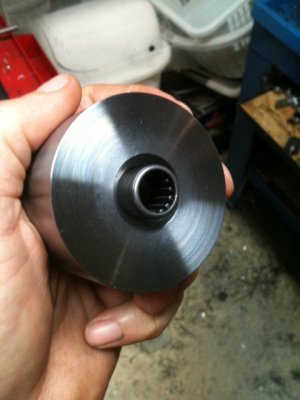
We're getting close to home stretch. The thrust and radial needle bearings arrived today. All that's needed now are the wave spring washers and oil seals. Hopefully they'll arrive soon.

You might have noticed how the finish of the of cap faces are rainbow smooth toward the OD but get splotchy close to the center. This is due to the SFM decreasing due to the constant decrease in effective diameter as it faces. On these pieces, I use auto crossfeed and increase the machine RPMs with the VFD to keep it perfect as possible. Since it's not a critical surface, I'm not too worried about it. If you ever watch the high-end CNC machines, you can hear the motors revving like crazy as they get toward the center. Some higher end manual lathes have a CSS (Constant Surface Speed) option to handle this.

Some pics...

The thrust bearing just sits in there and doesn't require a tight fit. I gave it 5 thou clearance around the OD. There are two hard/smooth pressure washers that that come with the bearing set and they sandwich the needle bearings. The wave spring washer will fit in the cavity and press against one of the washers. This bearing is rated for 8,000 RPM and 4,000lb force. That must be some seriously hard metal... -Not planning on coming anywhere close to those levels. I'd love to see how they make those...

T1.JPG

The radial bearing is also a slight interference fit. In this case, I was shooting for 1/2 thou interference but it came to 4 tenths -still good enough to hold it in place. The bearing has about the same rating as the other one. The larger OD around the bearing is for the oil seal which is 0.25" wide and 0.999" diameter (weird size). That cavity is 0.255" deep and 0.997" diameter. I'll drill the 5 holes tomorrow. The mill was tied-up with something else today.

T2.JPG

... Until next time ...


Ray

T1.JPG T2.JPG
 
Back
Top