9A renovation

Timken Bearings CLeaning & Restoration

I've begun the process of renovation. I'll post some photos and video later but I'm at a sticking point--literally. I'm trying to remove the right-side lead screw support bracket by removing the 2 slotted screws on top of the lathe bed in order to slide the bracket off the lead screw.

I can't get the screws holding the bracket to budge, despite using a very large screwdriver. I'm beginning to strip one of the screw heads as a large chunk of metal came off. Should I get a propane torch and heat the area? Pour Coke on it?

Any solutions would help me substantially.

I anticipate having a lot of other problems, as I'm not experienced in machinery. However, the machine looks really dirty and when I removed the oil plug below the carriage, no oil came out!!

So I'm thinking that despite my anxiety, it's best to continue and ask questions here, as I think I can get all the help and advice I need right here.

One other quick question. I want to start cleaning the parts I remove and painting them. The enamel paint only comes in a quart and a gallon, nothing in between. Would a quart do 2 coats of paint for the lathe or do I need a gallon?

Thanks!

Dave V

Happily following your restorative project on a great piece of American Iron.

As I am in the process of restoring an Atlas 618 lathe with the best of old
parts, I am particularly interested in whether you will be cleaning and lubing
the Timken Bearings.

I started with an NOS lathe bed. The spindles I got on eBay. Using brass and a rubber
mallet I safely have driven out the two bearings.

It is amazing the chips one finds in the racers. Lots of cleaner, .016 steel pick, and tweezers
removes copper and aluminum micro chips.

Prior to reassembly, I seek the advice of the experienced on this site on how to oil/repack the
bearings. The Timken information ranges from green bicycle bearing grease to engine oil -10/30.

Like a proctoscopic exam, one should not attempt it one's self, even if you have a mini-cam. :)

This advice and guidance will be handy to all Atlas restorers.

Thanks.

p.s. For the housing I fashioned a scraper from an old chisel and surprisingly it is getting rid of all
the multi-layer-hacker paint, all the way down to the bare metal. Soon I shall be priming and then
matching the original gray. Any painting advice, also?
 
Topos,

I read a bit further in my Ilion "Guide to Renovating SBL, A,B,C and 10K" (I always read and reread sections before attempting anything later on) and I'm pretty sure the SBL9A doesn't have thrust bearings (Timken style) on the spindle. That honor goes to the 10K, which was build, I think beginning around 1950 (although I could be mistaken on all counts). From what I read, the bearings used in the A,B and C are bronze, although during the war I think cast iron was used. Again, I'm no expert, just from what I read thus far.

I'm doing the renovating without painting. I plan to do a restoration once very 10 years and will consider paint next time. I've also got to restore all the wiring and possible clean the motor (GE A-C, model 5KC63AC494 1/2HP 115V 7.5A 1-phase, 1725 rpm and a reversing controller by Furnas, style RSB4). I'm collecting all the info I can on that, as there are a lot of cautions, such as putting too much lubrication in the motor, etc.

Regarding the drag link socket, I believe the fit will be better than the screwdriver I was using and very small ratchet with the driver tip that broke off. These drag link sockets from Sears look much more substantial and able to take torque without shattering. At least they appear to be.

Incidentally, I'll be doing a series of videos to try and help others and hopefully return the favors of all the help I'm getting. I'm going to Korea Apr1 to 15 to see my inlaws so this thread will be dormant for a while at that time.
 
I just finished cleaning and repainting my SB 9A, used a small Snap-On drag link socket on the troublesome screws you mentioned. I found that a firm, steady pull on the ratchet handle did the trick. Regarding the spindle bearings, during WWII South Bend simply bored the headstock to size and used no other bearings, at least on the 9", don't know about the larger sizes. Mine is a 1946, and the spindle runs on cast iron. As for that 40 tooth gear you mentioned, that is just a storage place for it, if you will look at the threading chart you will see that for the coarser threads the 40 is used in place of the 20 on the stud. Regarding the Timken bearings on the Atlas, when I had one I found that packing the bearings with #2 multi-purpose grease worked much better than using oil, including reducing vibration. Hope this helps.:))
 
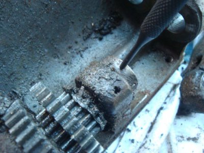
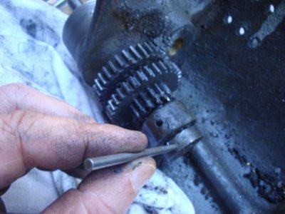
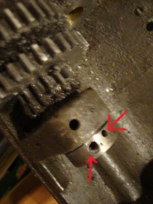
Hi all, had successes this weekend with gearbox except for one very troubling problem---taper pin on screw gear shaft collar. I tried driving it out with a harbor freight punch (1st photo), which broke, the next punch I used was a PTD HS USA one (2nd photo) and that didn't break but with all the force I was using, i was afraid I'd break the shaft. I applied propane torch and did the usual, then tried to drill it out. More problems. Red arrow shows the drill bit wandered out and now it appears impossible to remove the collar from the shaft. Any help much appreciated!

I've got nearly a dozen more taper pins to remove and I'm really dreading it! I'm thinking of replacing them with set screws.

DSC02149.jpg DSC02150.jpg DSC02152-copy.jpg
 
Hi Dave,
Following this thread with interest. Regarding your gear that is only in it for the free ride, you have change gears there that need to be swapped out for "other" change gears for different feed/screw cutting rates. That gear you have highlighted is probaly just backed onto another gear as a compound, but is not being used as such in this particualar application. The previous user just needed one half of the gear to equate his situation.
As for the set screws. Dont! They are not a suitable substitute for the applications where tapered pins are used!
Whilst it seems that corrosion has been a problem on your machine given the trouble you have had with screws, you need to persevere with penetrating oils, heat and persuasion. Are you sure you are getting the taper from the correct direction. One of the plusses for taper pins is that once they have moved, even just a tiny bit, is that they should be loose in their hole.

Cheers Phil
 
Thanks, Phil, there's a possibility I may have been pounding the wrong side. I carefully measured both ends with calipers and the small end is the end I pounded away at, which I thought to be correct. This morning, however, I did some internet searching and found that the small end might have actually been disguised. Let me explain. The big end was protruding and looked like a half-dome. I'm thinking now that I should have filed that half dome off to get the true radius of the taper. Now I know but it's too late to pound it out as I've already made a drill hole on each side, and as I mentioned, the drill went askew (even though it was done in a drill press). I'm thinking more drilling could cause the shaft to fail? Fortunately, nothing is connected at that end.

I would simply clean it as is assembled and not try to dissassemble it. However, one of those pesky wick passageways is hiding behind the gears and I really need to get to it to clean it out. Some of the wicks btw were missing and others were so badly corroded they looked like lumps of grease.

Also, the shaft still will not budge even after drilling, probably b/c the drill wandered sideways and a portion of the taper is still stuck in there. There's now no way to remove the residual part.

----

on the other topic, there's no longer a taper hole since I drilled it out, so the only option now is a set screw, unless I'm missing something. Something is inherently wrong with the design of using a taper pin on a shaft and then having to pound it out. The shaft definitely must be absorbing some of the shock from hammering and that can't be good.

---------

did a lot of internet searches and it seems I botched this more than anyone ever has possibly done
 
Last edited:
Now On To Spindle's Timken Bearings

By methods of advanced cowardliness and observation I successfully removed the
the 618 Timken bearings by prying off the protective covers with a dental pick, then
using a brass bar of same diameter and rubber mallet easing out the bearings.

It was no surprise that the bearings had a rough sound as I rotated them.
Proceeded to wash, blast and repeat with WD-40 and Teflon spray until they
moved freer but still hit high spots.

Using finest feeler gauge I probed racer while rotating. Surprise ... pieces of metal
shavings, including some copper showed their shining faces. Surgical tweezers and some hand-stands later
removed the pesky pieces resulting in the bearings finally running effortlessly and noiselessly.

Following Atlas data sheet I soaked and rolled them in Castrol 10/30 GTX.
Finally all was as it should be. I did use 10,000 grit Nagura Stone polishing paper with oil under finger pressure
to burnish the track of the outer racers. Even I know not to use a Dremel. :)

Having two extra spindles [ I do believe in back up! ] I performed the same operations on
the remaining three Timkens. Fully restored.

As the spindle on my operational Atlas 618 rolls quietly and noiselessly I will wait until
I need to change the belt to check out those bearings.

In summary, using the springy spark plug feeler gauges to insert between the rollers
and rotating was the critical part in the clean up.

For myself, I believe that one must be a demented miniaturist to enjoy lathe restoration but
it surely beats lying under a 1970 280SL removing and reinstalling the oil filter
with a 17mm ratcheting box wrench. :) :)

Thanks, guys, for your inspiring work.
 
Glad you got that done. I did discover that the 9A has a thrust bearing at the end of the spindle shaft in head stock, so I misspoke earlier, thinking it was only in the 10K

------

thanks 1200 for the encouragement. I might need to figure out taper pin sizes and where to get taper drills.

-------

Despite my frustration at taper pins and possibly screwing up the screw gear shaft, I promised I'd let you know the good news.

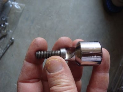
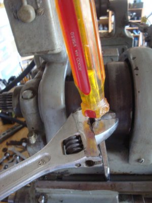
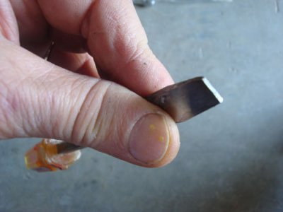
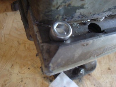
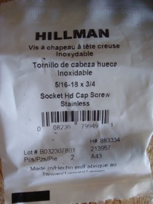
First off, I managed to remove the gearbox. The drag link sockets I ordered were all too wide for the slotted screw, as you can see in the photo; this is the smallest of the set. So I jury rigged my own device using an old square shanked screwdriver. I filed down the end until it was flat and held it and the bolt up to the light and kept filing until no light shown thru the bolt (the bolts I had removed from the tailstock side, which are same type). Then attached a large crescent wrench to the square screwdriver shank and put a lot of down pressure on the screwdriver and managed to turn all 3. I then purchased socket hd cap screws, which I plan to use to replace every slotted screw I ever see in my life.

---------------------

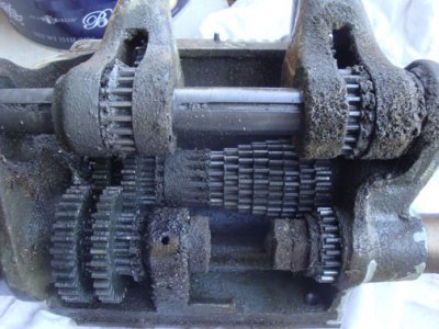
Except for the screw gear shaft and gears, which are still not removed, I did manage to remove everything else from the gearbox.

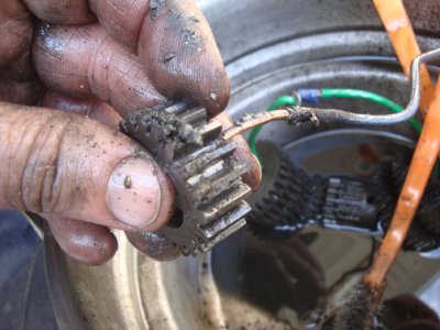
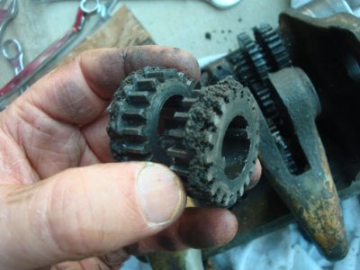
In 1 of the photos you can see how crud built up. Some of that crud in the gears couldn't be removed with wire brush so you can see I used a 12 gauge copper wire to remove the crud.

--------------------

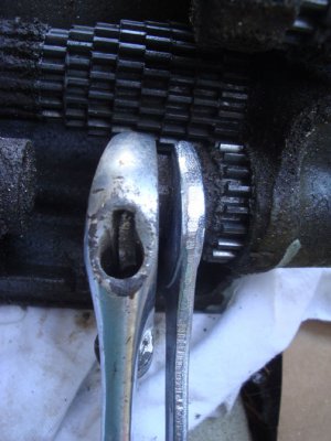
It was a bit tough removing the lead screw from the gearbox. in the photo, you can see I used a 7/8 box wrench and crescent wrench to remove the outside nut. However, when removing the inside nut, the gears spin when you try to turn the nut and when you hold the gears with gloved hands they still spin. So I stuck a brass rod in the gears to jam them and removed the inside nut that way. I'm not sure if what I did is considered proper or not.

---------

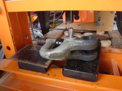
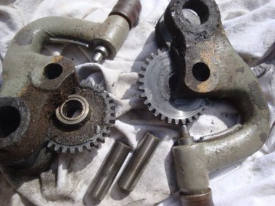
As you can see, my shop press came in handy removing tumbler gears.

---------

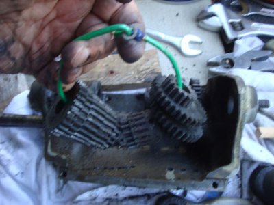
As for the gear tree on central shaft, that taper pin came out easily and you can see I kept them in order on a wire for cleaning

----

tonight I'll try to deal with that taper pin I mentioned about an hour ago. Hope I don't destroy the shaft and collar. You probably can't just go to Ace hardware and pick up new ones LOL

DSC02095.jpg DSC02096.jpg DSC02097.jpg DSC02104.jpg DSC02113.jpg DSC02146.jpg DSC02157.jpg DSC02160.jpg DSC02162.jpg DSC02163.jpg DSC02164.jpg
 
I had to use an air hammer on some of my pinss.

LOL, well not really but still...

1200:

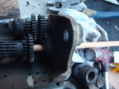
thanks on the handmade tool comment. I actually made a couple other handmade tools including this wood dowel to drive out a couple of shafts on the gearbox. I didn't have brass or aluminum in that size and the wood worked well enough.

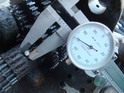
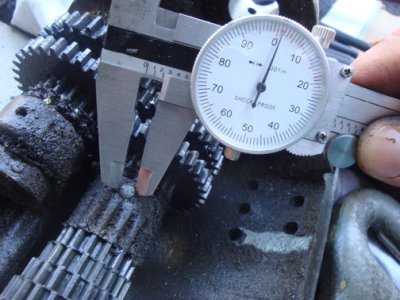
The taper pin on the gear tree, as I mentioned, went really smoothly. I used a caliper. Never before used it and don't know how to read it, but I looked at the gauge in metal and the dial and measured one end of taper as 2.01 and the other 1.70. Don't know if that's inches or millimeters or whatever.

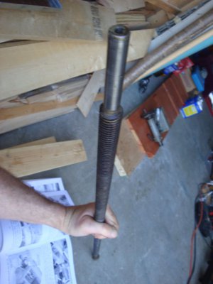
Hoisting the lead screw was a time for victory. Hopefully I didn't permanently bend the leadscrew when I took the 3 screws out holding gearbox to the bed. I placed wood under it but it rolled back and the leadscrew sagged..

Now, if only I can get the screw gear shaft out life will be sweet (probably at least until I get to the apron, headstock and motor, the dreaded motor and wiring).

Did I mention the gears were full of crud? Photo...

DSC02125.jpg DSC02136.jpg DSC02138.jpg DSC02140.jpg DSC02144.jpg
 
Back
Top