9A renovation

Hi all,

Back from Korea, snowed first week I was there. Enjoyed kimchi and soju.

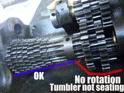
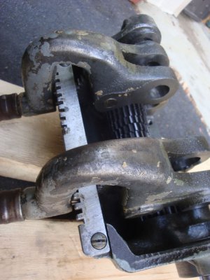
Returned and reassembled the gearbox. One big problem I noticed is that the gears on the central shaft that connect with the gears from the top shaft are locked and don't spin (see red line area). (I didn't connect the assembly to the lathe, just hand spinning test). As well, the tumbler on that side does not engage in any of the holes. It follows the keyway OK but comes up short about 3/8" from each hole.

I'm puzzled what is causing this and definitely want to find out before proceeding any further.

The gears on the other side as well as the entire central shaft rotates freely by hand (blue line area)

The top gears all rotate when they are not hooked up with the gears on the central shaft.

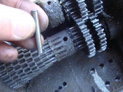
BTW, the photo with the writing was taken as I was in the process in driving in the central shaft so that is why the last 2 gears are not yet seated. As you know, I snapped photos of each and every step.

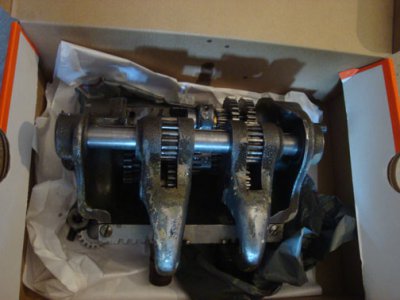
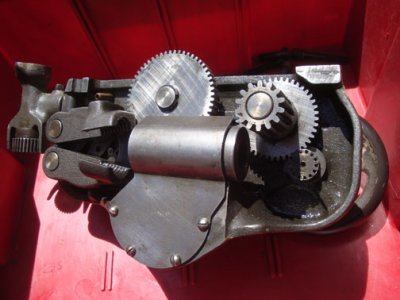
I'm also attaching a photo of the gearbox before it was dissassembled and cleaned. All gears are in the correct size and sequence.

Any help would be most appreciated as I thought I was so close to finishing this component!

Cheers

Dave
DSC02141.JPG DSC02989.jpg
 
Dave,
Are the tumbler arms on the right side, this will cause it to not engage right as they are right and left.
Paul
 
Hi Paul, yes. They are correctly positioned. I don't have a final assembly photo but they are as they appear here, obviously with the gears and shaft in them.

Even when the tumblers are moved away from the gears, they still don't move.

Therefore it appears there are 2 problems which may or may not be related).

1. The tumbler on the side with the red line is not engaging in the holes

and

2. The gears immediately where the red line is are not rotating, irrespective of the tumbler engaged or not engaged

I'm sure the problem is very elementary and I'm not overly anxious at this point. I just wanted to see if anyone could figure out what's going on. My best guess is that somehow the gears are not correctly meshing, but I double and triple checked to ensure all the gears are in the right place. As a last resort, I may need to take everything apart and put it together again.


(in the photo with my red and blue lines, the taper pin was installed as were the tumblers with gears and shaft--just a reassembly photo).

DSC02987.jpg
 
Dave,
There could be a couple of things to check. If I remember right the 2 tumbler gears might be different. The main shaft gears should move by hand as long as the tumbler gear is away from it, and check to see if the tumbler gear lines up with the other shaft gear when lined up with the plunger in a hole. There are 2 gears that are alike and one is on the short shaft near to the case side and the other is on the main shaft in the same place. One is just a tad thicker than the other and would cause a real tight fit on one shaft at assembly. Another problem is the shaft is binding or just needs to be cleaned a little more to make it rotate easier. Maybe the felts are binding the shaft too. I hope this helps.
Paul
 
thanks, Paul, I'll check when I get home tonight. As I mentioned, all the shafts rotate, it's just the gears where the red line is on the central shaft. As you know, the gears on that troublesome side of the shaft are not fitted to keyways so the shaft can rotate without the gears rotating.

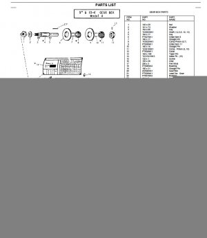
Since some gears look so similar, I'll have to find a book that has measurements that are precise so I can recheck that as well. It will sort itself out I'm sure.
 
found this so looks like I'll be counting teeth; LOL

Screen shot 2012-04-18 at 2.39.18 PM.jpg
 
Everything checked out OK, nothing was in the wrong place. All I did was to disassemble and assemble everything and now all is good and life is fine.

Picked up a 4 lb deadblow and 2 lb brass hammer from Harbor Freight yesterday to bang in the dowell pins, taper pins and shafts. Good prices and the hammers seem to be the same type you get at more expensive stores.

Also, picked up a very small grease gun from there for when I get to the cone later on. By mistake I picked up a box of metric grease fittings. I think they should have been imperial type.

So, dear friends, I'm ready to tackle the next aspect of the lathe dissassembly. I think the apron and saddle is next but I'll have to check my book.

The gearbox took a lot of time, but in the process I learned a lot and feel I'm better for it.
 
You are doing a great job there! I restored my 9A last year but did not completely tear down the gear box and apron, a good rinse with solvent was all that was needed. Without a specific problem or need to replace one of those gears I saw no reason to take them all apart. However, the clutch assembly tends to get loaded with swarf so that should be disassembled. And, of course, the spindle, headstock, cross feed/compound should get a complete teardown. I have the original GE motor too and it ran so well, I just cleaned up the end felts and oilers. I wouldn't be surprised if that motor lasts another 67 years!


There is a lot of good info in this 9A restore thread:

http://www.practicalmachinist.com/vb/south-bend-lathes/1947-model-9a-128005/index2.html
 
Last edited:
Hi Martik,

Thanks for link. Glad your GE motor is doing well. At the end of this renovation I plan to replace wiring and try to determine how best to clean it up. Runs like a charm.

Regarding the gearbox, I took it apart mainly b/c it was dirty and to replace all the wicks. If I hadn't broken it completely down, I'd have never gotten to those areas. The 2 hardest things on the gearbox looking back on it, were the taper pin and lining up all the gears on the keyway doing it blind. Book says to mark teeth with marker but markers just don't mark on gears b/c of the oil. If anyone knows of a better way to mark gears, I'd sure like to hear about it b/c later in my build there will be a time or 2 I need to do it again. If you're off just a tad, you risk damaging the keyway on the gear and on the shaft.

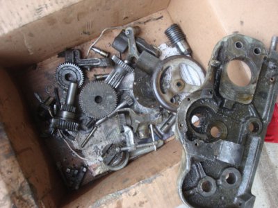
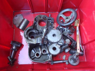
As each component of lathe is taken apart, I oil it up. In this case the Q/C gearbox is oiled with B oil and placed in a shoebox along with the nuts and gear that will go on the leadscrew at a future point in time.

Yesterday I dissassembled about half of the apron and stopped when I started getting tired. Will resume that teardown this week. Sometime today I'll try to post photos and a description of how it went (went well). However, none of my photos are uploading at this time.

cheers

Dave
 
well, looks like the photo thing is done so I'm back, like it or not :)

The gearbox is back together after being taken apart, cleaned and rewicked. It is in a shoebox now. Reverse gears are in another shoebox. And finished the apron this weekend and it too is in a shoebox, cleaned and rewicked.

I've gone into great lengths about the gearbox so now a chat about the apron...

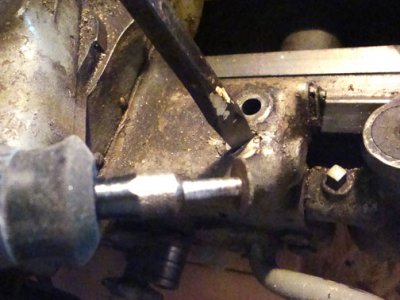
The slotted screws holding the apron to the saddle were a real B***** to remove so ended up cutting a deeper channel with a small dremel wheel, just enough to get the blade in deeper

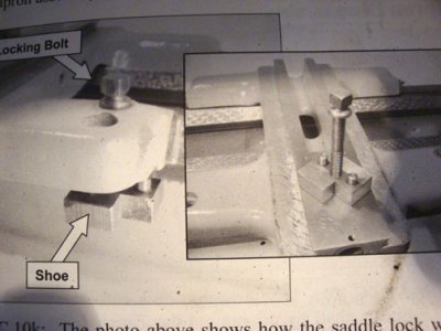
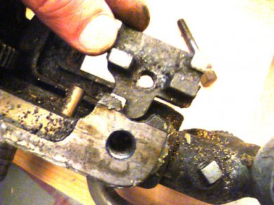
The saddle locking shoe picture in the book is different than my saddle locking shoe (see book photo vice the shoe I'm holding). I'm told that the shoe I have is an earlier version (1942).

The book completely left out dissassembly of an important component. In file photo DSC03122 (last photo showing the assembled and cleaned apron), the apron in the red box, look to the extreme left. There's a vertical component with a gear attached at the lower end. I don't even know what it's called, but it was mentioned nowhere in the lathe dissassembly book. I had to remove it in order to remove the long pin that is pulled out through 2 holes (I forget the name of that pin, but it is in DSC03052 file photo protruding through a giant hole)

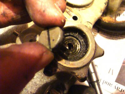
I managed to unscrew the screw from the star wheel. It unscrews clockwise. The book mentions this, which is helpful.

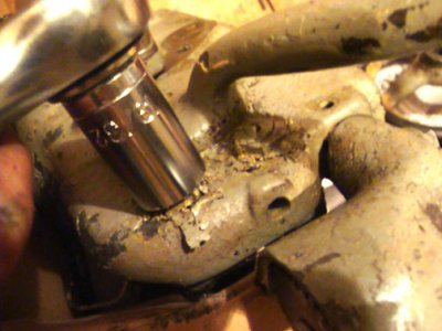
I've come to conclude that paint is nasty. It flakes off and gets into all the parts. See the photo of the wractchet. I wish there was no paint on the lathe and eventually I may try and remove all of the paint and just keep a light coat of oil on the lathe, similar to cast iron cookware. Paint is NASTY!

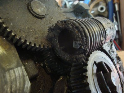
I'm including some before and after photos showing gunk and cleaning after.

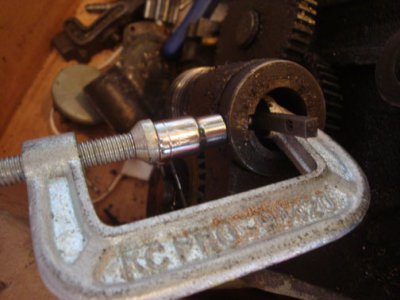
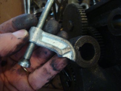
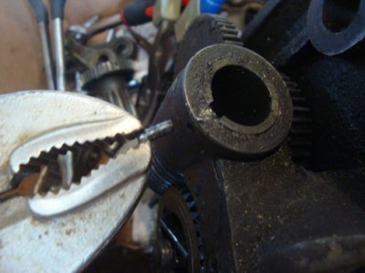
The tiny pin that holds the collar to the worm gear shaft was another B**** to remove. I used the procedure from the book, using a 1/4" socket and a steel clamp to remove it. Guess what? The clamp broke and I had to get another clamp to remove it. Then, I had to work it out with a vice grip. It was a real pain!

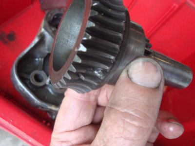
Lastly, 2 teeth on clutch gear were damaged. I thought about throwing a bead of weld on it and filing to profile but enough of the teeth remain that it should be no problem engaging the worm. I discussed this with some others and showed photos.

So, everything is assembled, new wicks, gasket with RTV blue, and next we go to the saddle. Haven't started yet. Need recovery time between components!

DSC03004.jpg DSC03006.jpg DSC03015.jpg DSC03018.jpg DSC03042.jpg DSC03045.jpg DSC03063.jpg DSC03069.jpg DSC03073.jpg DSC03076.jpg DSC03112.jpg DSC03113.jpg DSC03116.jpg DSC03122.jpg
 
Back
Top