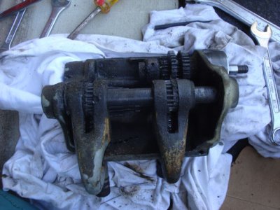
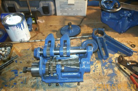
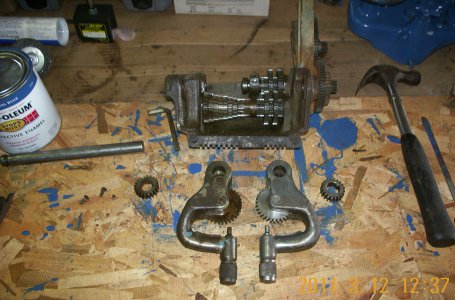
9A renovation

btw, the book mentions an oil cap on the gearbox chassis. Says there's "a pressed in plug on the right side of the casting. To thoroughly clean the gallery and to provide future access...drill out this plug, thread hole with 5/16"-18 tap and install 5/16"x1/4" set screw...teflon tape on threads to prevent leaks"

Has anyone tried to do this? Is it worthwhile doing this? I can't even find the pressed in plug on mine; must be I need to scrape away paint.
 
I used a caliper. Never before used it and don't know how to read it

Dave,
Dial calipers are pretty simple. Yours are imperial.
On the main body, (non sliding part) of your calipers is the inch scale. You will see that each inch is divided into 10 smaller segments, numbered from 1-9, and repeating the number order each time you pass a major inch.
Open the calipers, wipe the inside faces of the 2 jaws that contact each other when they are closed, and then close them together.
Now loosen the small knurled screw at the bottom of the dial and rotate the dial case until the pointer is on zero. Your dial indicates in 0.001" (or each tiny division on the dial is 1 thou). If you use the thumbwheel located to the lower right of the dial and roll it counter clockwise, (it is a friction drive so you need to press up with your thumb as you do), you will see the pointer rotate clockwise. One full rotation of the pointer is 100 'thou or 1 tenth of an inch. If you look now at the chamfered front edge of the sliding jaw you will see that it is indicating on the 1st division. These numbered divisions keep track of how many times the pointer has gone around. When you get to 1" the pointer will have gone round 10 times.
You did read it almost correctly. The measeurements you have taken are 0.170" or (170 thou) and 0.201" (or 201 thou).
The knurled thumbscrew at the top back on the sliding part is tightened to lock the caliper when you have taken a measurement and dont want it to move. Dont overtighten it and leave it loose when storing the calipers.
The spiky pieces that slide past each other on the top side of the caliper are for measuring inside dimensions.
The long tail that slides out the back end of the caliper is used for measuring the depth of holes and such, so try not to damage that either.
You may have found a small piece of shaped flat brass in the case with the calipers. This is used to slip the pointer pinion if the dial is out of whack. ie pointer is not at 12 o'clock when jaws are closed.

Cheers Phil
 
SE18,
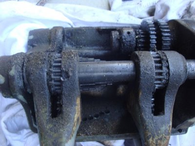
On my 9A gear box the taper pin part sticking out is the big end and should be hit from the other end. The tumbler arms are right and left, so don't mix them up, I kept mine on right and left side so they would be right and still got them switched around. When I got my lathe my gear box was stuck shut and would not turn due to dried oil on shafts and the taper pins were facing the wrong way inside the box. The only thing that worked was a small ceramic heater on the gears for a little while until I could turn the gears by hand and then knocked out the taper pins. Three or four hands would make it easier to get the gear box back together, as it is a little tight in there while trying to hold everything together and keeping it lined up.
Paul

DCP_0456.JPG DCP_0450.JPG
 
Hi pjf134,

Nice looking gearbox. Stupid question time. I see you painted yours (and nice job, btw). For those not painting their lathe and have large areas where the paint has come off, will this make the metal more susceptible to rust or should one put a light coat of oil on this metal (similar to seasoning a cast iron pot)? The only problem is it might attract more dust unless you use a dust cover.

Is my logic on this tracking?


On your gear shaft, the taper pin is not completely round so it might have gotten whacked in the past.

-----

OK, 10-4, your tip on left and right tumbler arms, INVALUABLE! Didn’t know about this. Fortunately, I’ve taken photos (see attached) of the entire process and by the paint signature, I can see which will be right and left during assembly. I’m fairly certain the book I’m reading doesn’t mention not mixing them up (it only states not to confuse the gears, but I think the gears are interchangeable right and left? Come to think of it, after looking at the photos, it appears that the shape of the R and L tumblers are different? See how it pays to take photos during the entire process!!!

It also helps, I've found, to have different buckets. For example, in one bucket is the reverse assembly and in another bucket is the gearbox assembly. I've been doing some internet surfing and am finding out that a lot of people who buy used lathes see broken teeth on gears. I was curious what causes these teeth to break. Perhaps incorrect assembly or not putting a gear lever down all the way (not properly engaging gears), or perhaps locking the gears and removing the chuck, which stresses the gears? Anyway, it would be good to know to avoid this from happening to me!


I’ll try my hand again at removing that stuck taper pin sometime this week or weekend, but will make a trip to hardware to get some taper pins and taper drills. Might need, sure I need, to increase taper pin diameter if I ever get that taper pin removed! I still think set screws would work better but you’all have advised against it so I’d rather listen to experience than go it alone.


I did sometimes wish I had a few extra hands. My wife, btw, was furious at how dirty my hands got and told me to wear latex gloves next time, which is kinda girlish, LOL


Small ceramic heater? I think you lost me there.


Oh, btw, I'm going to pick up some pipe cleaners. If I ever get this gear box dissassembled, I can see where they'd come in handy for cleaning out those hidden oil passages. Did I mention the gearbox resembles an object filled with wormholes.


Hi Phil,

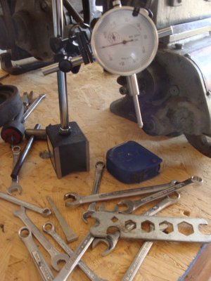
Thanks for the treatise. Among supplies ordered from Harbor Freight is this dial indicator (photo), which I haven’t yet used. I assume it probably works similarly. BTW, I didn’t see the small brass piece in the caliper case.

Someone said that a micrometer is more accurate than a caliper so eventually that will be on my list of things to buy once this lathe is disassembled and then assembled, which will be at least a few months away. LOL
DSC02009.jpg DSC02122.jpg DSC02123.jpg
 
Last edited:
Hey, I feel your pain about needing more hands while working on that gear box. My hands are sort of oversize anyway, and I had a heck of a time trying to get every thing in place. Amazing how much trash and swarf can find its' way in there. Plus 1 on the pipe cleaners, I smoke a pipe, so I've got lots of cleaners, including the bristle kind. Invaluable for scrubbing out oil passages and the other hard-to-get-to places. Regarding the taper pins and reamers, I had to get mine from MSC, as there were none locally. I'm sure there are less expensive places to buy them, but I've bought from MSC for years, so that's where I went. Going oversize on the pins is OK, no harm done.:))
 
Thanks, I'll probably need a bigger taper pin and a taper drill. Anyone know what sizes on both and the cheapest place to order them. I probably need a couple sizes, original and maybe 1 or 2 sizes bigger on the pins and bits. It's really a shame that recessed hex bolts or something could have been used. It would have made life a lot easier for me and others who've had taper pin headaches. I don't think they use them in modern-day machinery.
 
Dave,
That little brass strip is'nt always supplied with calipers. I have one with my Mitutoyo dial calipers but not with my cheapo ones. So maybe they come with the better sets, I dont know? I just mentioned it in case you had it but did'nt know what it was for.

The reason for using taper pins in assembly is for "precise" location of parts. The parts are assembled at the factory to exacting tolerances and then drilled and pinned. By drilling a tapered hole, when parts are reassembled, the taper will allow for small errors to be pulled back into perfect factory alignment as the pin is pressed home. Having mating parts on either end that need to be reassembled exactly could not be achieved using set screws.
Taper pins also do not allow for any movement of parts in relation to one another after installation due to it becoming an interference fit on assembly. A screw or even a dowel pin or key cannot provide that level of security. Thread tolerances that allow the set screw to be installed mean that there must be clearances allowing for possible movement. If a dowel pin, or key and way, had the interference that a taper pin provides then assembly would be impossible.
Taper pins are still in common use in industry today on parts that need precise alignment.

Cheers Phil
 
SE18,
Take another try with the taper pin, it may come out. The little heater was for heating the gears so I could turn them and get to my pins that were facing the wrong way. You could try that with the pin, as the shaft will expand with heat and just maybe the pin won't since half of it is gone. The cast will rust when bare and it all depends if you have rust issues on bare parts in your shop or not. When you use way oil on the lathe when done wiping it down after using you could do the same for the bare parts on the cast parts also. When you have the lathe tore down it would be a nice time to paint the parts, I did paint almost everything I could since it way easy at that time. I also did one assembly at a time so I would not wind up with extra parts at the end and wonder where they go. Gears break from abuse and there is many ways to do this. Always turn off machine when changing gear box gears or back gear. Make sure gears mesh properly when putting together, loose fitting gears will slap a tooth or two when running like that. More to come as you get further. I hope I answered your questions.
Paul
 
thanks, Phil, Paul, great argument for using taper pins. I'll go to MSC and some other sites and order a bunch of taper pins and taper drills.

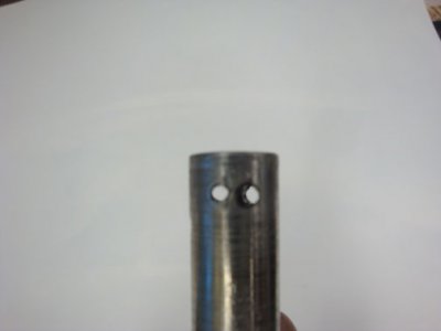
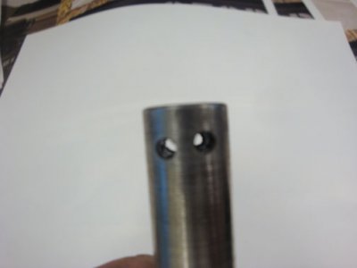
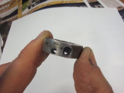
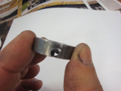
Last night I removed the shaft, but it wasn't pretty as you can see from the pictures. Don't look at the photos if you are in any way squeemish.

One hole on the collar is perilously close to the edge. Photos show both sides of collar and both sides of the shaft.

Now, how to proceed?

Please tell me if this plan has merit or if you know another way, other than buying new parts:

clean holes of cutting oil with soap and water and pipe cleaner. Dry. Then fill holes with JB Weld, putting masking tape on all sides after so it doesn't run out. Then proceed with taper drill either in one of the holes or make a new one. I'm concerned though about making a new hole as metal fatigue could result. Thusly, I am thinking to go with small taper so that hole doesn't get any larger. The JB Weld would give me a chance to do that. Unless there's a better product (If I knew how to weld, some hot metal in there would work)

If I use a taper drill on that hole you see on the collar, it will probably collapse the wall (last photo shows how close that hole is to the edge).

You can see I've created a fine mess. All b/c of that taper pin, parts of which are still inside after the drill bit wandered around on me.

Eager to hear any constructive advice.

-------

Paul,

Question regarding gears and preventing breakage. I'm guessing you should wait until the machine comes to a complete stop before throwing the drum switch into forward or reverse from the other direction. Also stop when making any other changes to levers and anything. Are there any possible lever combinations that could cause harm, perhaps like not engaging the half nut when threading or turning forward with gears locked, etc? I kinda would like to know the answer to that down the road once I start actually using the lathe.

Dave

DSC02188.jpg DSC02189.jpg DSC02190.jpg DSC02191.jpg
 
Last edited:
Dave,
On your machine you should stop machine when changing gears and also when using reverse, some motors will let you reverse while running, but on yours I would not. Reverse is seldom used because reversing spindle and cutting could unscrew a threaded chuck, so I would just not use it to be safe for now. For threading you should engage back gear, pull the pin on the bull gear and engage half nuts while running, could be done while machine is off also, but we will get to this when you get to that point. Only use half nuts when threading, use the power feeds all other times to save the threads on half nuts. Keep in mind the thread dial needs to be set with the lead screw and marks on the dial, we will get to this later when ready for it. Make sure the gears engage right, not to tight or too loose, will assure yours gears last. Your drilled out collar should be OK for reuse since there is hardly any forces on it
Paul
 
Back
Top