Beauty in The Beast: Webb 5BVK Barn Find/Conversion

Well - I don't (completely) blame you for the confusion.
Keep in mind - there is an element of unknowns for me - and there is also an element of discovery for all of us.
I ran the test - exactly as you prescribed - and it delivered some interesting results.
I probably listened more carefully than you realized.

You noted that I should watch out for big jumps that might be caused from a single burr or hole - so I made sure that I wasn't measuring that.
But my understanding of that direction had its own consequences.
When I saw the sudden jump of the indicator needle - I assumed it must be the burr or hole you warned me about.

I made sure not to measure that exact point when giving my readings.
It never occurred to me that the sudden jumps were something other than specific small issues in the taper surface.
Until the tech showed me - "hey, if it was a hole or a bump, then when I reverse the spindle with my hand - it should bounce back the exact same way"
That's when I cottoned on that I had an erratic issue - rather than just a surface issue with the taper.

It's a process.
 
Spent the weekend using the mill.
Will share a little as it shows some pertinent machine performance and my (lack of) know how.

Before I jump tho - quick update on mill runout.
I have my feelers out for a reasonably priced quill rebuilder.
Though I joked about it in my last post, any readers of this thread are aware that Extropic anticipated and correctly diagnosed a bearing issue.
Tech was to test for that before he ground the spindle - but only detected the issue afterwards...
Painful - but sometimes in a war... you take a bullet.
¯\_(ツ)_/¯

I am hungry to to get my scooter back on the road, so tackling the fix with the mill as is.
As noted - finding center is a challenge - but I came up with a means to deal with the run out.
Not sure if it is machinist approved - but It appears to be working for me.

Issue with my scooter motor cases is a worn out main bearing seat and a "rotary pad".
In simple terms - the rotary pad must sit .05mm (.002") off the outer edge of the crank web.
My plan was to center the cases, and do both jobs off that center to stay concentric.
At issue was finding an accurate center.

How I approached:
First I center the cases with a coaxial centering tool.
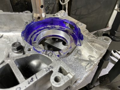
Next, I blued the cases and put the boring head in.
I then put the mill in neutral - so I could spin by hand, and rotated the boring head.
I continued to sneak it out by .001 until I got first contact on the cutting surface.
If it didn't touch the same surface 180° opposite - I would move the axis.
I repeated this - .001 out with the boring head, check for touch on 180° surfaces - until I got touch on both sides.

IMG_4804.JPG

Once I managed to find center in this fashion, I cut both surfaces.
IMG_4810.JPG

My knowledge on speed and feeds is weak - but measuring of the holes after processing showed they were round to within .01mm or .0004".
That surprised me given my runout - but none the less - it was a good surprise.
I also learned the hard way not to try it slow - when the boring bar grabbed the case and moved it on my first attempt...

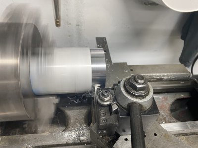
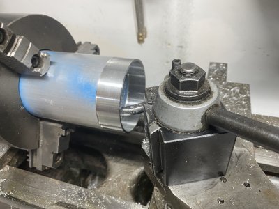
I made a couple parts on the 10EE lathe - which reminded me what a pleasure it is to work with a tight tolerance machine.
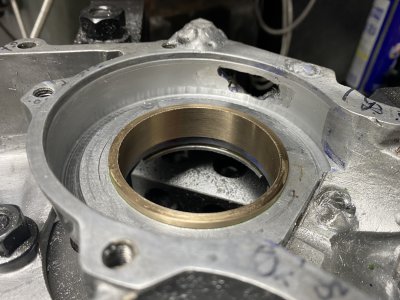
The brass BRONZE part is press fit - and needed to be .1mm (.004") oversized for the hole I cut. Was amazed that I was able to hit it.
The aluminum ring will have a section cut out of it for the inlet pad I previously noted.

IMG_4825.jpg

I pressed the brass bearing in after heating the cases - and it is not coming out...
IMG_4833.JPG


Couple observations.
I used the Jim Dawson rest my hand on the Y axis trick to keep on center.
X didnt seem to want to move around as much.
While the Mill is clearly not right - there seems to be a kind of consistency to its run out? The bored holes seem quite concentric.

Jim - can you remind me - the new system - will it in some way keep the motor engaged to hold on a spot?
Also - with no tacho on the servos being used - how will it know it's position?

Excite to get to the conversion - just have to finish this project and find a quill repair shop first.
Perhaps with a little luck - I can do the quill work and conversion in parallel in parts if not in whole.
 

Attachments

  • IMG_4806.JPG
    IMG_4806.JPG
    2.7 MB · Views: 3
  • IMG_4815.JPG
    IMG_4815.JPG
    3 MB · Views: 3
  • IMG_4829.JPG
    IMG_4829.JPG
    3.2 MB · Views: 3
  • IMG_4819.JPG
    IMG_4819.JPG
    3.2 MB · Views: 3
Last edited:
nice! Quick Q though - is that brass bushing actually a bearing surface? Or is it a spacer to hold a bearing? If it's a bearing surface you might want to press it out and redo it in bearing bronze :)
 
Jim - can you remind me - the new system - will it in some way keep the motor engaged to hold on a spot?
Also - with no tacho on the servos being used - how will it know it's position?

The short answer is: The magnetic scales are fed directly to the controller and will be able to detect any attempted movement, the controller will then signal the drive to apply torque to the motor to correct for that within the 1 micron resolution of the scales. The tachs on the motors are fed back to the drives only and are only used for velocity control and have no real function in station keeping. My machine normally holds +/- 1 micron when position holding.

The longer answer is: It gets into motion control theory, PID loops, commanded position vs. position error, and loop speed. Entire books are written on this subject. And I don't feel like writing a book today. :) And I am busy proving out my latest code changes to make sure my lathe CNC code is 100% compatible with the Haas ST-10 lathe post processor that I'm using now with my C axis installation, where I used to use the older Haas Turn post processor that did not have C axis and mill/turn capability. There are some major differences between the two. Oh and maintaining backward compatibility so I don't have to repost some of my older G code files which were partially hand written. o_O
 
nice! Quick Q though - is that brass bushing actually a bearing surface? Or is it a spacer to hold a bearing? If it's a bearing surface you might want to press it out and redo it in bearing bronze :)
Mathew - its a "spacer" then a steel complete bearing is pressed into.
It is actually Bronze - did I type brass? Oops. At least I actually spec'd the right thing in action.
The short answer is: The magnetic scales are fed directly to the controller and will be able to detect any attempted movement, the controller will then signal the drive to apply torque to the motor to correct for that within the 1 micron resolution of the scales. The tachs on the motors are fed back to the drives only and are only used for velocity control and have no real function in station keeping. My machine normally holds +/- 1 micron when position holding.

The longer answer is: It gets into motion control theory, PID loops, commanded position vs. position error, and loop speed. Entire books are written on this subject. And I don't feel like writing a book today. :) And I am busy proving out my latest code changes to make sure my lathe CNC code is 100% compatible with the Haas ST-10 lathe post processor that I'm using now with my C axis installation, where I used to use the older Haas Turn post processor that did not have C axis and mill/turn capability. There are some major differences between the two. Oh and maintaining backward compatibility so I don't have to repost some of my older G code files which were partially hand written. o_O
You had me at: the magnetic scales are still used and feed the controller directly.
Great! (I thought that was the case but then started to question my understanding).
Thanks for taking a moment.
Good luck with the lathe CNC compatibility project!
I'm off to try and find some HSS in small size I can weld on to my 3/4 boaring bar to get into a tight space...
 
Last edited:
Quick check in here.
Work and a project (which I am using the mill for) have my conversion to CNC on temp hold - bit longer than anticipated.
Have a few more parts in - but need to collect the rest of them from my list.

Some real discovery from using the mill on this project, and a question.

On discovery: I have been pleasantly surprised how well I can get it to perform a boring task.
The measured run out seems manageable - when doing it by hand.
Not to say I don't want to have it repaired.
Below are the motor cases I am working on.
There is a replacement pad I fabricated on the 10EE lathe - and welded into place.
I then put it on the mill and centered - using bluing ink to fine adjust so that the bearing bar was basically cleaning the ink off evenly around the perimeter.

I then cut the pad so that it would have a certain clearance to the crank shaft that gets inserted.
Pic's worth 1000 words - so here is one
The green arrow points to the welded in pad that I subsequently cut to a tight tolerance clearance to the crank shaft.IMG_4920.JPGSo the discovery is that I have been able to mostly workaround my issue, at least with boring.
That may not be the case for other process.

The question:
My machine has a central oiling feature.
I have been just using a by hand method - but it struck me I wasn't accessing the precious spindle bearings.
Further - I noticed that the oil line that is feeding into the head has been disconnected.

I assume my lines may be clogged in places.
I would at minimum like to feed oil into the spindle for the short term.
How does one ascertain if they are getting oil into the spindle bearings?
(I assume I could use a syringe to try and "pump" some oil in to the tube that goes into the head.
How might I treat the lines to get them primed with fresh oil?
Welcome some thoughts - can provide more pics if needed.

Thanks,
-CM
 
For flushing and leak detecting or visually looking for flow through lines I like to use ORDINARY ATF. nothing special. It has the ability to clean.
Of course you will need to flush this out as well.
Any pictures I have the same machine but with the A/B controller.
I received zero documentation but I can follow the lines.
 
The oil line to the head most likely only lubricates the Z ball screw and maybe the quill. The spindle bearings are most likely greased at assembly and not lubricated again until rebuild. Continuous lubrication of spindle bearings is normally only found on high speed spindle machines.
 
For flushing and leak detecting or visually looking for flow through lines I like to use ORDINARY ATF. nothing special. It has the ability to clean.
Of course you will need to flush this out as well.
Any pictures I have the same machine but with the A/B controller.
I received zero documentation but I can follow the lines.
Good stuff. Wouldn't have thought of that. Also - can finally get rid of the bottle of ATF that is next to my oil. . Thanks!

The oil line to the head most likely only lubricates the Z ball screw and maybe the quill. The spindle bearings are most likely greased at assembly and not lubricated again until rebuild. Continuous lubrication of spindle bearings is normally only found on high speed spindle machines.
Ok - that makes me feel better - was starting to consider what kind of damage I might inflict (not that they aren't due for refurb...)
Good insight on where continuous feed normally resides.

With the two above responses - I am fairly confident I can trace and flush all the lines - then refill the reservoir with my fresh Vactra #2.

While I am hear - I have been wondering about researching/doing some unconventional machining to clean up the edges of my motor cases.
Wonder if there is a name for what I am thinking of (cant wait to see some of the responses to that one... stupid/dangerous/hair brained...)
First - the goal:
When I reworked these old cases - I had to do a significant amount of build up with weld material on some warped and damaged areas.
IMG_4916.jpgThat area circled in green eventually had weld material built up to fill it all out.
I then used a surfacing tool to re-surface it - the results of which are below.
IMG_4920.JPGThe red arrow shows how some of the weld material now overlaps into the inside of the case.
For speed and simplicity - what I would LIKE to do - but thought I would ask about is this:
- Bolt cases to a heavy base that can slide on my table.
- Put 2 flute end mill in and spin at relatively high speed.
- Slide the base with the cases around BY HAND to trim back the edges nicely, tracing back to where they should be and giving a nice defined 90 degree edge back.

Fear of course would be the work being grabbed - slung - ruined - etc.
Is this madness - or is there such thing as "free handing" on a mill?
(teeth gritted for the responses. let them rain).
-CM
 
I would clamp the work to the table and use the x and y to move it.

Maybe you already said but what kind of engines are you working on? I used to build racing kart engines.

John
 
Back
Top