SB Rehab/Restoration

NAPA said my v-belt is a Browning Super Grip B41. 41 being the length in inches. I only have the single speed motor pulley on both of my 10L's though. So not sure of the length you would need with the 2 speed pulley.

Sent from my Samsung Galaxy Note 3
 
Last edited:
Guys yesterday afternoon the paint was drying so I decided to make a cover for the motor junction box,the original is MIA.The motor being alittle handycap since its a 3 footer and not 4 I just could not let it go necked with wires expose,so what do I have to lose other than time.
I found me apiece of 16ga metal,took some measurements of the cast iron back plate cut the metal to size allowing 3/16 over hang all the way around to bend over for a lip.Guys I'm sorry I can't keep a straight face.I watch "This Old House"and Tom Silva hollers out Cut off 3/16,it sounds so dramatic.Well the lip end up being what it is but its close to 3/16 or maybe its 1/4.

Guys I did luck off cause the lip that I bent using my torch and a piece of angle iron as a back plate in the vise work pretty good.

Using my bandsaw to cut out the parts for the cover and my die grinder with a cut off wheel to cut out the center piece except one end which I bent it up with the help of my torch.Then using the little mig welder,I spot the pieces in and tack them in place.The flap that I had left I heated it and then bent it over the side pieces then tack them in place.

Since my welding looks like a dirt dobber done it,I use the grinder to clean up the welds then check for holes and weld again.I will take my sanding disc and clean it up,then paint.Thanks for looking----kroll
 
Last edited by a moderator:
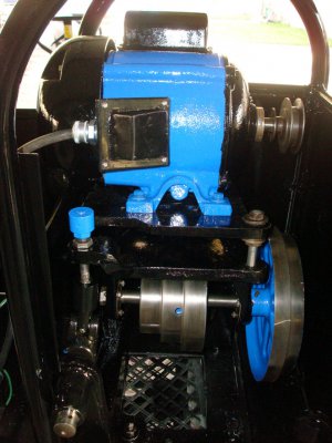
Spent the last few days assembling the motor mount and installing and wiring the motor just like it was when taken apart.Today was a successful day till I gave the motor a try in rev using the drum switch.Not knowing if it work in the past or any history on its previous life if it was wired for 110v or 220v and no motor plate on how to wire the motor.Guys I wired it for 110v cause the cord cap was 110v but that don't mean there wasn't some rigging going on,who knows??All I know is reguardless the position of the drum switch the rotation is the same.Now I'm wondering if the motor may have been wired for 220v with the wrong cord cap,way its wired right now the motor draws 10.3 amps @ 110v which seems high even for this monster size motor.The motor does run smooth and quit and feeling of the motor around the bushings its just as cool as air temp after bout 15 mins run time.Guys I'm at a guessing point on this motor and I don't want to burn it up wiring it for 220v just to see,so any ideals??? I'm sure this is the same motor as other lathe of this period w/drum switch,anyone have a diagram so that I can compare???Thanks guys---kroll

DSC02221.JPG
 
It shouldn't matter whether you wire it at 110v or 220v, as long as the motor is single-phase. Most can be wired at either voltage. 10 amps is in the range of what a 1hp motor should draw...I think. It's a common issue to not be able to get the motor to reverse right off the bat. Been there...done that! There are threads all over the place about it, but every motor is different.
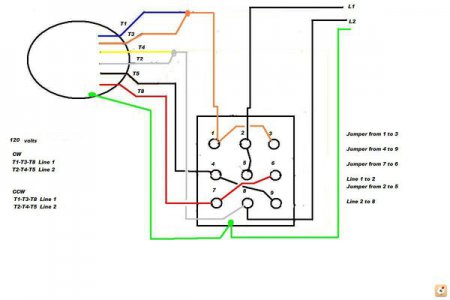
I have a good diagram for the basic 8-wire motor to drum switch configuration, that I attached as a jpeg. If it is too small to read, pm me and I'll email it. It might help, it might not.

Sent from my Samsung Galaxy Note 3
y3ujunut.jpg

y3ujunut.jpg
 
Last edited:
Thank you Cuseguy,is #5,#8 the capacitor?I took the leads apart this morning and they are lable #1-#4 then two yellow wires which go to the capacitor maybe through the centrifugal switch,I think---kroll
 
Honestly this is not my field of expertise! Your guess is as good as mine. An electrician friend made this out for me, back when I had the same issue that you have, and it has worked for me ever since.
It looks to me like T2 and T3 are your start windings, so aren't those the cap wires? I could be wrong as I said though. That's why I use VFD's now....so much easier!

Sent from my Samsung Galaxy Note 3
 
Or are the capacitors T1 and T4?
 
Last edited:
We need someone that actually knows what they are doing:)
 
I only add to the confusion,this is one area I hate asking questions cause I have a hard time understanding,but the diagram makes sense.Later this morning,I'm going to ohm the motor windings and see what is what.The yellow wires are not number so I though it made no difference which terminals #4 or #7,when I had the cover off of the cap the wires were also yellow:whiteflag:
 
Back
Top