Tachometer Kits / Installs

When I installed my tachometer I just used a 9 volt battery to power the tach. My drive had a contact that closed when the drive was running so I used it to turn on my tachometer. The only time the tach is on is when the drive is telling the motor to turn. No risk of leaving the tach on and running down the battery. So far I have not had to replace the battery yet so I do not know what the battery life will be. Simpler than wiring a power supply.

Just my 2 cents
Roger L
 
Hi Roger,
Nice idea. I did something similar with a sensor control for turning on our garbage disposal. There the power required was 220V 20Amp circuit. I turned the disposal on with a Solid State Relay and turn on the SSR with a Reed switch via a set of 4 AA batteries. The Reed Switch is closed via a magnetic field and I placed it under the counter top out of sight and out of the water etc. No electrical switches exposed. My wife has a very small, decorative, flower vase on the counter with the magnet inside and she just moves it over the sensor to turn on the disposal. Anyway, the only time power is taken from the batteries is when the disposal is running. I installed it around 2011-2012 and have yet to need to change the batteries. I also wired in a three position toggle switch so that I could turn it on manually (no batteries), turn it off completely (safety), or only allow the magnet to run the device.

I have been thinking it would be nice to have a tach on my lathe spindle, but hate to attach a magnet to the spindle. I am curious how you mounted your tach sensor and magnet.

Dave L.
 
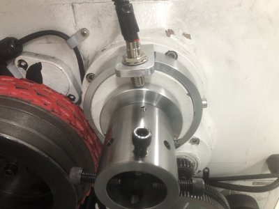
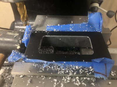
Attached are some photos of my install. I have an Automation Direct VFD in the box I made to hold it. The tachometer power is wired to a relay output from the drive the the tach only works when the motor is running. The lathe is a South Bend 11 swing. The headstock has the 7/8" hole thru it. I made an aluminum adapter that I pressed on the small hub on the gear at the end of the spindle. The magnet holder attaches to the adapter with a small setscrew. The prox switch is mounted to the guard. I needed to machine the guard a little to get a flat surface for the prox switch mounting block to mount. Lots of work to get the magnet and switch to mount but there was no better place to put it.

Thanks
Roger L

IMG_7488.JPGIMG_7490.JPGIMG_7491.JPG
 
Thanks Roger,
Nice install.
Maybe I can try a press fit a magnet holder on my lathe. I will have to check it out to see where I can attach the sensor. I have not been able to find a Tach with a smaller display. I have a purchased a volt meter type display that is about 69mm x 26mm. My VFD puts out a 0-10Vdc signal corresponding the the maximum motor frequency,which I have set to 100 Hz. I.e 10 volts = 100Hz. However, this is not really the spindle RPM as one changes gears. It will fit in my lathe control panel, but all of the tach readouts I can find are about twice this size and do not fit very well.

Good night
Dave
 
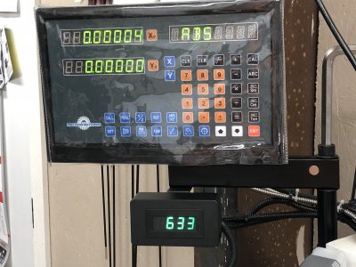
Finally got around to finishing my tachometer project. Lots of credit to Mark for the technical advise on connecting the power supply and producing the spindle collar with magnet. Fit like a glove. I went with a different approach on the reader support collar and made one out of stock material from McMaster. Took very little machining.

Multipurpose 6061 Aluminum Round Tube, 1/2" Wall Thickness, 4-1/2" OD

As it turns out, the PM1236 spindle rotation is 10-15% faster than the chart.
 

Attachments

  • IMG_8821.jpg
    IMG_8821.jpg
    1.6 MB · Views: 139
  • IMG_8818.jpg
    IMG_8818.jpg
    1.6 MB · Views: 145
  • IMG_8840.jpg
    IMG_8840.jpg
    1.4 MB · Views: 148
Finally got around to finishing my tachometer project. Lots of credit to Mark for the technical advise on connecting the power supply and producing the spindle collar with magnet. Fit like a glove. I went with a different approach on the reader support collar and made one out of stock material from McMaster. Took very little machining.

Multipurpose 6061 Aluminum Round Tube, 1/2" Wall Thickness, 4-1/2" OD

As it turns out, the PM1236 spindle rotation is 10-15% faster than the chart.

I installed one of these in both my lathe and mill when I did my 3 phase motor / VFD upgrades. They take a few seconds of running before they display an accurate speed, but work rather well considering the low cost.

I found and used 120v versions from Amazon, as my lathe only had 240v and 120v ac transformers in the electronics enclosure. My contactors all have 120v ac coils.

A short video overview.

 
Back
Top