Need some help reading and understanding this electrical diagram

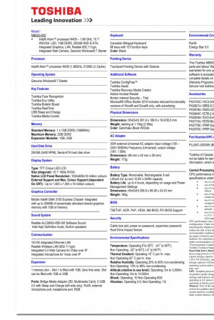
I have tried to boot with the Linux USB but not having any luck. Are you saying I should remove the hard drive that has windows 7 on it and booting from Linux with out the hard drive installed in the machine? That is the only thing I have not tried yet. The machine is a Toshiba NB500
No, I was describing what you apparently have already tried. What kind of problem(s) did you encounter when attempting that?

One thing I ran into with an older laptop was some issue with the distro needing some functionality that the old CPU didn't have. I found a distro called "puppy linux" that is compatible with older CPUs, and that worked OK on the old Dell.

IIRC the versions that worked the best on the Dell were "wary" and "precise". They are 32-bit versions. I tried the most recent 32 bit version of Ubuntu and, while it worked, was just too slow.
 
Try to contact the vendor and ask for schematics if possible.. also look for burn marks or any discoloration in the solder in the legs of the elements where they connect to the board
 
Just reading the post here but to understand it better you have a Toshiba NB500 that was slow and want to install Linux on it.
1. Is windows still there can you boot into it.
2. What Linux distributions have you tried booting so far.
3 do you have any of the original usb/cd/dvd that might have come with it.

For 1 list on the device manager all the devices it has installed or use any free tools to generate a list of drivers.

For 2 If the Linux live usb does not boot then.
A. either the bios is not configured to work properly
B. Linux distri does not have the drivers

For A you can get the screenshots and share here
For B you might need to look into getting the drivers to the live Linux usb and configure them to load at runtime.

This is what I can thing for the moment.

Tim
 
The diodes have a safe reverse voltage so unless you kept it running it should be ok change the caps as the might have been damaged. It does not seem to have any IC in there. Max you will have to go old school and pull the elements out and measure them one by one. Also try to get a proper schematic. Also check the resistance of the transformers winding. Without a proper schematic as the others have said it will be pretty difficult in troubleshooting. Do you have the serial number tags etc from the unit or the pcb front back etc. post them here and I will give them a look
Here are pics of the board. You can see one of the Varistors is cracked and the cable connector has soot on it from when the Varistor popped. You can see the board is marketed by Align and has the part number on it on front and back. Thanks for the response. IMG_2010.JPGIMG_2006.JPGIMG_2007.JPGIMG_2008.JPGIMG_2009.JPG
 
Back
Top