Had a bit more progress since the last update that I'd like to share.
I focused on the crankshaft next. Remember that this is a 5 piece press-fit assembly (two shafts, two discs, and the offset pin). My buddy got a start on one of the discs which I lightly cleaned up

The second disc was cut to match the first. I had to make the OD slightly undersized from the print to get them to match. The CCMT insert worked great for this heavily interrupted cut. The bore was reamed to 0.624"

I had to take some time to think of how I wanted to cut the offset pin bore such that each disc had the exact same throw and the webs in the castings were aligned. Any error in the throw of the cranks (relative to eachother) would create a misalignment of the end shafts and they would bind in the bearings.
To accomplish this, I hand punched and drilled a tiny hole in the middle of each of the webs visually.

I then turned and sanded in a 0.6238" arbor that was a tight sliding fit to the bore of the discs. Using a tiny drill bit shank to align the holes, I super glued the discs back to back.


The super glue firmly held the parts together for the remainder of the machining operations. I set this up in the mill. Unfortunately I did not have any Vee blocks that were big enough to hold the part, yet small enough to fit in the vise (this was a problem later on). I added a hold down clamp to make a hard stop I could push the part against. I cut off a section of the arbor to use as a pin to indicate the bore.

I first indicated at the base of the pin to find center of the bore, then used a sharp tipped chamfer tool to visually clock the part such that the webbing would be centered on the to-be-drilled hole. I did not yet take any care to accurately align the part to the machine since any effort there would be lost when I loosened the vise to clock the part.

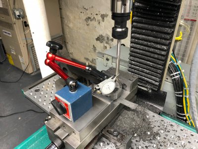
Next, using a tenths indicator, I swept the pin up and down to measure the angular alignment of the part in the vise and tap it into true with a lead tapper. This was time consuming and took about an hour. At the end of the day, I got it within 0.0001" over the roughly 1.2" length of the pin. Once it was aligned, I found center again.

Out of concern that the part might move when machining it, I gently placed a strap clamp on top, tightened to finger tight. This was a huge mistake I would learn later.

The hole was rough drilled

Then I threw in a under sized reamer to cut the precision .3115" bore. When I first mounted the reamer, it had 0.009" runout. Using a tenths indicator, I was able to tap the tool into runout <0.0005". I figure that the flexibility of the tool shank will allow the tool to center up once it hits the drilled hole.

Unfortunately, once I removed the part from the vise, I could see something was off. The hole wasn't right. I setup a measurement cradle on the surface plate, using the center bore as a datum and measured the hole was crooked by 0.002" in the radial direction and 0.008" in the tangent direction. I suspect between the addition of the hold down clamp, the drilling, and the reaming, the part must have shifted in the vise.

This amount of misalignment was not tolerable and would cause issues with the center shaft alignment once the assembly was pressed together.
It needs to be corrected... To be continued.


