Mike's SCARA Robot

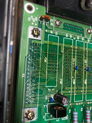
Does the track show continuity from end-to-end? (it looks like you've drawn enough of the circuit to know)

If so, I'd be tempted to just leave it.
You're right it looks darkened in that one area, but if it is not delaminating from the board you might create more problems by removing all those connectors. Is it noticeably burnt between connectors too? (say X50 and X40)

I doubt it could lift enough under the connectors to cause shorting.

-brino

It is open circuit right now.

It is darkened for the full length of the trace and it goes under each connector. I think it burned open under the X20 and X30 connectors.

I hadn't planned on removing the trace or removing the other connectors, but it found it lifting off of the board under X10 when I removed it. This worried me that it could lift under X20 - X50 as well and cause a short, so I figured I'd remove all the connectors. The heat must've destroyed the solder mask and the glue which binds the copper to the fiberglass.

I had good luck when removing the X10. I first added a bit of leaded solder to each lead to reduce the melting point and add a bit of flux. I then used the hot air rework station to heat the entire connector until it fell out. Finally I used solder wick dipped in liquid flux to clear out the plated through holes and prepare the board for soldering again. I don't like the idea of removing all the connectors, but I feel confident I can do a good job.
 
You've shown your skill and perseverance before!
-brino

Thanks!

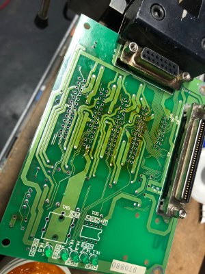
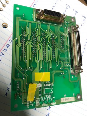
Connectors are removed. Pretty glad I did check. The trace was completely delaminated from the board and would have easliy made a short with a bit of vibration. I removed it entirely. I also found a single via hidden under the X30 connector on this trace. I would have missed this had I just cut the trace at each end.

I left this picture kind of big. The loose trace is hard to see. One piece is near the text "X50" and the other is near the text "26" on the X30 connector. Just past that blackened trace is the via I would have missed.

I have no clue what that 3 terminal orange device is in the upper right corner. +24V enters on pin 1 and exits on pin 3 to be distributed to all +24V power pins. The pin 2 is connected to a pin on the MDR/SCSI connector labeled "RG" which might be robot ground?. Maybe this is some sort of 3 terminal fuse. The component is labeled "NF1".
image053.jpg

It was a bit of a pain to clean out the plated through holes for the connectors, but with a full spool of solder wick, I got it done. Everything is ready to be soldered back on once my repair is done.

The brown scum is rosin residue which cleaned up nicely with some 91% isopropal alcohol. Really hard to find any right now!

image052.jpg

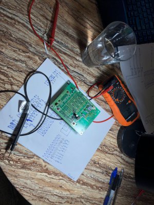
Spent the rest of last night drawing a full schematic for the board. I'm about 70% done. Most of the pins on the MDR connector just map straight to a pin on the rectangular connectors. A few of them, mostly power, homing, and brake control have some strange circuits. I'd like to have a diagram available in the future. It is also correcting my bad terminal labeling from earlier.

image055.jpg

Have to work the weekend, but hopefully I'll have some time after my shifts to get this finished and get the motors spinning again.
 
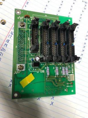
Circuit board is repaired!

I finished up the schematics for the board as well. Not sure if they are 100%, but darn close and plenty good enough for me. I forgot to take pictures, but I'll upload them tonight. The schematic drawing is embarrassingly sloppy, but that is because I drew it in the order of tracing the wires and not in any manner that conveyed function. I may still redraw it with a logical layout.

I used some 30AWG magnet wire to repair the board. This is rated to carry 2A while the original trace was probably good for 500mA. The diode (VD1) was replaced with a glass 1N914 diode I had on hand. I have no idea what the original ones were, but this is probably heavier duty than the original. The reverse breakdown voltage is rated for 75V and it will only be seeing 24V.

I needed to get the magnet wire from the top of the board to the bottom and I found the easiest way to do this was to feed it through the plated through hole that the diode is installed in (the wire also needed to be electrically connected to that leg of the diode, so it worked well). I also soldered all the connectors back in place.

The heat of the solder automatically strips the enamel off of the wire so soldering was easy. I had nice thin 1/8" kapton tape in the house somewhere, but I couldn't find it. I'll clean up the trace routing when I do.

image056.jpg

image057.jpg

The board was reinstalled and the polarity corrected on the brake leads. I nervously powered it on and the brake clicked open immediately! I'll install a small 500mA fuse on that terminal to prevent this from happening again!

I'll have to study the schematic I drew, but the brake circuit is a bit goofy. I think it always has 24V on it and the robot controller would have switched the connection between the brake return and DC common. There is also a button on the top of the robot that allows you to manually release the brake to lower the tool at the end of the robot arm.

I think this board is generic and can be reused for robots with additional motor brakes and/or absolute encoders. There are footprints to install additional components on the board that I think might have been switches accessible from the back window to define the absolute position on the encoder (if you purchased that option). I don't think that most of the traces are used for my particular robot. It was pretty strange to me that the 4 connectors which go to the motors were all different in the way they connected. I have to study the schematic to figure out exactly how they are different, but I would have thought that they would all be the same.

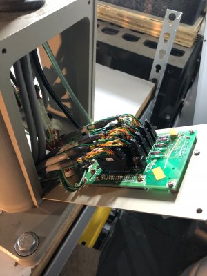
Here is the board installed in the back of the robot.

image058.jpg

I think I am ready to power this up and start running the Z axis motor on the Ultra 3000 as a standalone drive again. If this works, my next step is to swap the reworked Version 1 feedback adapter board for the Version 2 one. If this works then I will reconfigure the Ultra 3000 to accept an analog torque command and try running it from the PLC using motion commands.

If I can get past all of that, the next step is to solder 3 additional feedback adapter boards and startup the other motors. If that works then I can wire up the remaining 3 channels for the analog servo cards. Last step would be to run the entire system with robot kinematics enabled.

If I can get there (god willing), then I need to dream up a robot interface and program some sort of runtime program. I'd like this to be able to run a basic text language with a table of positions and instructions to use a tool. I can create this and copy from some robot control language. I'd also like to add a G-code interpreter to allow offline programming of more complex movements! This could be a couple months of work, but it sounds fun!

Once everything is working nicely, I'll probably repackage all of the electronics inside a big enclosure like I did for my CNC.
 
Had a very successful weekend with the robot. Only had about two hours to work on it but got a ton done. Here is what I did.

I am running out of drives that I have to play so I ended up using a mix of normal drives, drives with SERCOS fiber-optic option module, and drives with DeviceNET communications option module. The module is factory installed and shouldn't be removed. For the robot, the T1 and T2 axes are running drives with the SERCOS option module, the T3 axis drive has the DeviceNET option module, and the T4 axis drive is a plain standalone drive.

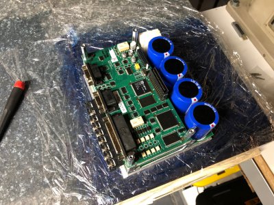
With the SERCOS module, you can disable it in software and use the drive standalone. I tried to do this with the DeviceNET drive, however that option doesn't exist and the drive was constantly faulted with DeviceNET Link Down since the drive wasn't on a network. I tried a bunch of different things but couldn't get the drive to let me run it. Eventually I got a tip that the option module can be ripped out of the drive and the drive "forgets" that it even had a module to begin with. I did this and everything was OK to run after that.

Here are the guts of that servo drive. The DeviceNET option module would have sat on top of those standoffs. The drive is a sandwich of 2-3 boards. The bottom board with the capacitors is the power module and contains the Isolated Gate Bipolar Transistors (IGBTs) which create the variable frequency motor output. Above that is the control module (visible in the picture) which is the brains of the drive. It evaluates motor command and feedback and generates the control signals to fire the IGBTs. It also handles serial communications and the I/O. This structure is the same for drives up to 2000W. Beyond that the frame size of the drive increases.

image059.jpg

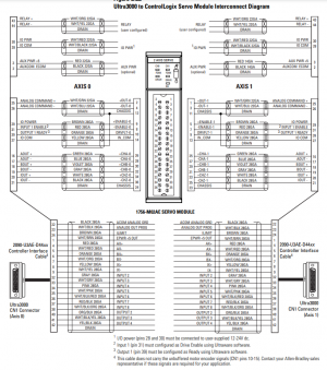
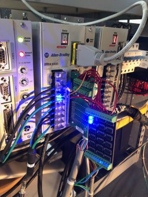
I setup the PLC rack with a new program to run the drives using the analog card and tried it out. I quickly found out that I didn't have the card wired correctly, and after a bit of searching, I found this very helpful graphic in the manual.

1600081220261.png

The big thing I was missing was the external 24V power supply. With that installed, I was able to hookup the enable and drive fault signals correctly. I ran the motor tests and tuned the system and it worked! Seriously this just went smooth as could be. The motor can be enabled and run using the PLC motion commands just as I needed. The motor response is very stiff and responsive. I ran a few manually entered commands and everything worked as expected.

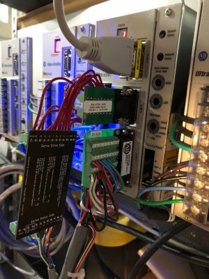
The next step was to remove the old feedback adapter board and replace it with the new one I got in the mail the other day and soldered up. I decided to not bother with scoping all the signals and just try plugging it in to see if it worked. I got really lucky and it worked on the first try! Pretty cool that I designed that circuit from scratch and it is now working as planned. I have to solder 3 more for the other drives, so I'll try to get some better pictures of the process for a follow up post.

image063.jpg

image064.jpg

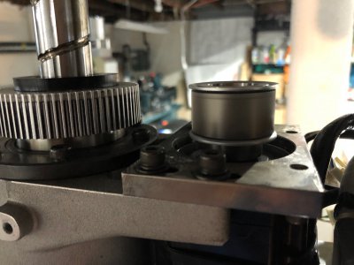
I identified the T3 motor has a 36T timing pully which drives a 72T pulley on the ballscrew for a 2:1 drive ratio. Motor is running in the image below

image062.jpg

I finished off the afternoon by writing a simple motion control program which raised and lowered the Z axis at around 50% speed ad infinitum. It is nice and quiet when running which is pretty cool. I get position error faults when running the motor above 2700 rpm or so. I did not tune with the load installed, so I should be able to get better performance with some diligence in setup.

View attachment IMG_9622.MOV


This is probably the biggest breakthrough I've had this entire project. Unless something is truly broken, the remaining motors should be a perfect copy of this axis as far as wiring and software configuration. I will be driving to get these done in the next week or so. The rest of the axes are very difficult to mechanically decouple from their gearboxes/loads. I'm going to try to start them up with the load connected and pray I don't crash anything! I finally see the light at the end of the tunnel.

-Mike
 
Last edited:
Since we are getting close to some robot action, I think now would be a good time to discuss the mechanics and kinematics which the software will need to handle.

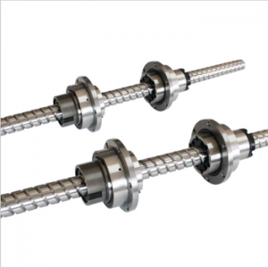
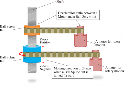
First thing to discuss is the T3/T4 motor assembly. The two motors are belted to the two nuts on the ballscrew/ballspline. The T3 motor drives the upper nut which is a traditional ballscrew nut. There is a 2:1 gear reduction in the belt system. The T4 motor drives the lower nut which is a ballspline (free to slide axially, fixed rotationally). It has a 1:1 belt drive ratio as well as a planetary gearbox with a currently unknown ratio.
1600090397079.png

The screw is able to translate and rotate with the differential motion between the two nuts. They follow the equations:
Z = (T3 - T4)*Screw Lead
U = T4
Where Z is the change of position in the vertical cardinal axis, U is rotation about the Z axis, T3 is the rotation of the ballscrew nut, T4 is rotation of the ballspline nut. Screw lead refers to the linear distance traveled per rotation of the ballscrew nut

Since the PLC is controlling the motors and not the end effector directly, we need to rearrange these equations to solve for the motion of T3 and T4. This gives the following solutions:
T3 = (Z/Screw Lead) + U
T4 = U
1600090225709.png

In the controller, the real motors are Servo Axes and the cardinal axes (X, Y, Z, U) are considered Virtual Axes. Virtual axes can be commanded just like real motors, but are only used for calculations. In the case of the robot, the Virtual Axes Z & U compute the motor axes T3 and T4. Virtual Axes X & Y are used to compute T1 & T2 through the built in kinematics functions. I may also add a Z_Rot virtual axis to handle the screw pitch calculation.

Currently the built in robot kinematics for the SCARA variety do not handle the Z/U interaction, so I will need to handle it in the code manually. To do this, I will need to electronically gear (does exactly as the name implies) Z_Rot to Z with the ratio equivalent to the screw lead. Then T3 will be electronically geared to both Z_Rot and U. T4 will be electronically geared to only U.

The gearing can be set in the startup routine. Once it has been enabled, it is continuously calculated in the background by the PLC motion planner. What this means is I can command motion on Z and U (in inches and degrees respectively) and the PLC will figure out how to move T3 & T4 to make that happen.

The motion planner also has coordinate systems. These allow you to add kinematics to your motors. Kinematics in robotics refers to the calculations required to convert desired motion in an X, Y, and Z Cartesian coordinate system (the one we are familiar with) to motion on the joint motors. These equations become highly non-linear and motion in a straight line in Cartesian space can create some very complicated motion at the motors.

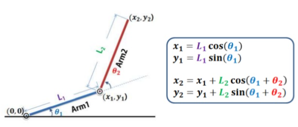
Forward Kinematics are the simpler equation to solve and the SCARA robot is one of the easiest geometries to do it on. With a basic familiarity in trigonometry you should be able to see how knowing the joint angles (theta 1 and theta 2 in this example) allow you to calculate the end effector position (X2, Y2 in this example). The calculations ignore the Z and U axes.
1600092397511.png

Inverse Kinematics are the devilishly complicated brother to the forward kinematics. With the inverse kinematics your goals is to determine the joint angles needed to give a defined end effector position. This is done using typically using Devanit-Hartenberg parameters and the homogenous transformation. This is usually a graduate level subject. Unfortunately I never got the chance to cover it in school, but I did buy a textbook and spent a year and a half studying the subject. It is still about as clear as mud to me :p . Shown below is a picture of the solution to the inverse kinematics for this robot.
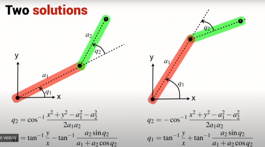
1600093709652.png

Notice there are two solutions. While going through the math, you end up taking a square root and introduce a plus-or-minus into the equation. This means there are now two equally valid solutions. In real life, this holds true as the robot can approach the desired position from two different angles and get perfectly valid results.

To make it worse, there are many positions within the workspace where one or neither solution is valid. This occurs when the motion required to reach that position is beyond the physical limitations of the mechanics of the robot (for example a position further away than the arm is long, or one near the right edge of the workspace where one of the solutions requires the arm to rotate further than it can go, but the second solution would be valid). The kinematics alone won't always help you find the right solution since they return answers without boundaries or limitations taken into account. The robot control software needs to be able to make decisions on the fly as to which solution is the appropriate one to use (think of cost minimization functions and such). With the PLC kinematics, you must select if you wish to use a right arm or left arm solution when enabling the kinematics. This can be switched at runtime but it creates a discontinuity in the motion control as the arm flips to face the other direction. You can see this happening repeatedly in the second video in post #4 of this thread.

In 6 axis robot arms it gets even worse. With all the extra joints, additional plus-or-minuses get introduced into the solution and you end up with 8 potentially valid solutions for any given position and orientation. UGH!

And after all of that, you have only figured out what the motor positions are to get the robot to a particular position. Let's say you want the end effector to move in a straight line in Cartesian space, you now have to consider path planning. This is done with the derivative of the homogenous transformation called the Jacobian. I never got to learning this by hand. But it allows you to create the non-linear function which the motor must execute to generate linear motion at the end of the arm through some god-awful math that looks like this:
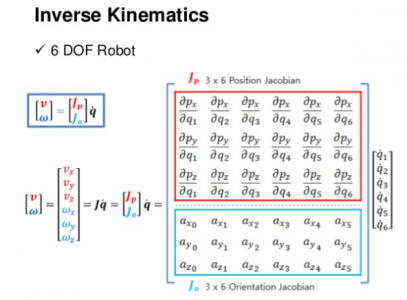
1600094409292.png

Thankfully, the PLC handles this part for you behind the scenes. All you have to do is command motion in X and Y like a CNC machine, and it will do all the math to make the motors move where they need to.

This is a super deep subject that makes me really excited, but I think I'll stop here before I bore anyone. If you want to hear more, or have questions, let me know and I'll make a follow-up post.

-Mike
 
Last edited:
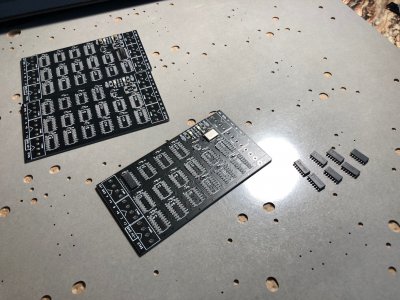
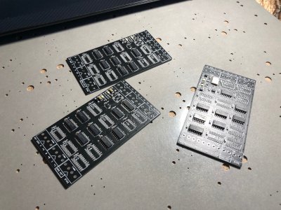
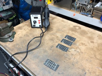
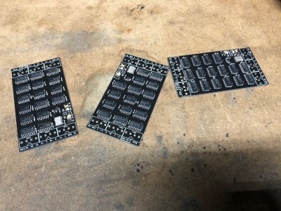
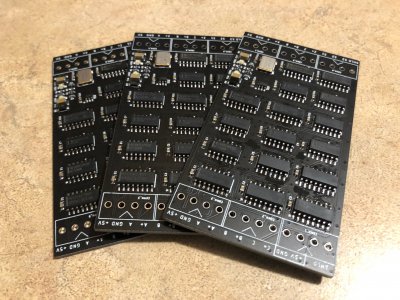
Finished the other 3 circuit boards last night which should allow me to interface with the remaining servo motor's feedback. As promised, I took some extra pictures to share my process for assembling surface mount PCBs.

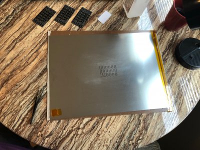
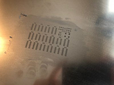
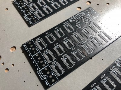
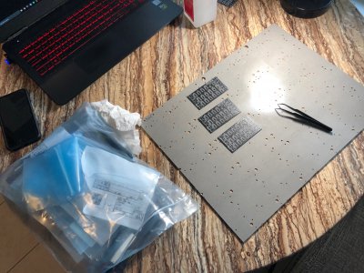
For the second set of PCB's I ordered, I opted not to have the manufacturer trim down the stencil. Instead I got the full size sheet (same price) with two pieces of hard paperboard with a slick coating. I think these are the backing sheets used on their CNC drill machines and they cut them up to use as packing material for their finished products. I used one of the boards and some kapton tape to build a hinge. There are two spare PCBs underneath to build a fence to locate the PCB to be loaded with paste. This lets me quickly load and unload many boards for application of solder paste without having to worry about alignment.

image065.jpg

The solder paste is kept chilled in the fridge. A credit card is used to squeegee the paste into the cutouts. Extra paste is put back in the jar.

image066.jpg

And here are the boards with solder paste applied. This did not turn out as neat as my first board, but it doesn't need to be a perfect paste job to get good results while soldering. Any wiggle or vertical movement of the stencil against the board will smudge the paste.

image068.jpg

For placing my parts, here is my setup. I used the other piece of scrap board as a work bench. I have the schematics up on my computer to help identify the parts to be placed. I am using antistatic tweezers to place the components, and all the parts to be placed are in the blue bag. I go through one component at a time and place all the parts that I need.

image069.jpg

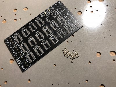
Here's (44) of the 0.1uF ceramic decoupling capacitors

image070.jpg

And a couple of the SOIC chips.

image071.jpg

Halfway done.

image072.jpg

An hour later I have all 3 boards populated and a 4th board with solder paste on it to use as a test article to dial in the reflow temp. I am using a cheap $30 reflow gun borrowed from a buddy. You can dial in both the air temperature and the air flow rate. I reflowed at 350*C and 4/10 on the air flow. I spend about 3-4 minutes heating the board with about 4-5" of clearance. Once the flux in the paste is melted, I know I am close to the melt temperature. From there I place the heat very close to the board and quickly reflow the parts.

I found it important to heat the capacitors quickly otherwise the pads would melt at different times and the tiny capacitors would tombstone (see link here). Once the tiny components are well flowed, then I can take my time with getting the bigger components to reflow. I work in a wave across the board, allowing components ahead of the heat gun to preheat a bit more before I get to the for final reflow.

I take one last pass at all the IC's at a 45 degree angle to the board to clean up any stubborn solder beads that didn't fully melt if they were hidden under the chip. Then I let the boards cool for 10 minutes.

image073.jpg

All soldered up. At this point, I use a copious amount of 91% isopropyl alcohol and an old tooth brush. The flux dissolves in the alcohol and can be rinsed away after several washings. This also cleans up any miniature solder beads left from the solder paste. The better your transfer of paste at the stencil phase, the less cleanup is needed.

image074.jpg

All Done.

image076.jpg

I soldered on the connectors after this by hand, but didn't take pictures. The next step is to wire up the T4 motor and try to get it running. If I can do that I'll get the Z/U kinematics programmed and then move onto T1 and T2.
 
Great work as usual Mike!
:clapping:
You certainly master both the theory and the practical of your projects.

After all the tense work of placing parts and waving around the hot air blower, wouldn't it be nice to have a robot arm to do that next time? :big grin:

-brino
 
Great work as usual Mike!
:clapping:
You certainly master both the theory and the practical of your projects.

After all the tense work of placing parts and waving around the hot air blower, wouldn't it be nice to have a robot arm to do that next time? :big grin:

-brino

Thanks Brino!

I actually thought that would be a fun first or second application once I get this running. Maybe make some cheap circuit boards with 555 timers to make a few LEDs blink. I imagine that the parts would need to be moderately big to have any success in placing them. Circuit boards are so cheap, so it would be fun to try!

I also thought about trying to program it to assemble little lego cars over and over.

Now that I got one motor working, I am really excited to start the programming.

-Mike
 
Back
Top