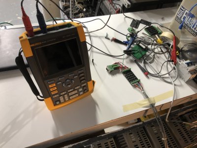
Mike's SCARA Robot

An hour of placing SMDs with forceps? I'd pass out from lack of oxygen well before that.
 
I use one of those little vacuum pencils thingys. designed to pickup and position SMDs. There cheep and work very well. Still tedious and exacting work
 
An hour of placing SMDs with forceps? I'd pass out from lack of oxygen well before that.

It was an oddly zen experience. Been doing work on a laptop 10 hours a day so it was welcome to do something with my hands. I had just mowed the lawn 10 minutes before I started, so I was expecting my hands to be shaking like crazy with these little parts, but I had great success.

I use one of those little vacuum pencils thingys. designed to pickup and position SMDs. There cheep and work very well. Still tedious and exacting work

Ooohhh! That sounds awesome. Might need to get me one. Where'd you get it?
 
I use one of those little vacuum pencils thingys. designed to pickup and position SMDs. There cheep and work very well. Still tedious and exacting work

Ooohhh! That sounds awesome. Might need to get me one. Where'd you get it?
@Boswell , I too would appreciate if you could provide a link.
Thanks,
-brino
 
Wife and I are both working 10-12 hours a day, 6 days a week right now. I'm exhausted - BUT this robot has given me a kick in the pants to get it working! I've felt quite stuck for a while, and now I am making quick progress. Fun feeling. I want to spend all my free time on it.

I got a few hours on the robot yesterday and was able to get the T4/U axis motor running. I'm hoping all the remaining motors require roughly the same effort, because this wasn't too bad.

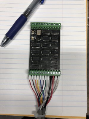
First step was to wire up the feedback adapter board to the terminal blocks on the robot. There are two cables in the bundle, one is 9 conductors and contains the encoder signals and power output to the encoder. The second is a larger two conductor cable which connects this board to the 5V PSU.

Image077.JPG

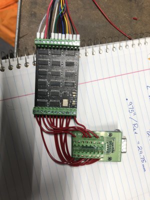
The adapter board is then wired to the feedback breakout board which plugs into the drive. I wish this was a one piece assembly, but it works for now.

Image078.JPG

I ohmed out all the connections all the way back to the motor at the end of the robot and confirmed the connections were correct. I really screwed up the numbering on the terminal blocks relative to the robot manual, so I need to carefully double check every connection by hand.

I powered on the drive and tried the encoder, but absolutely nothing worked. I even got the scope out and was ready to start tracing signals. I was super bummed my feedback adapter board wasn't working. I didn't have the mental energy last night to try to trouble shoot the circuit.

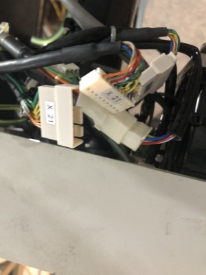
That's when I realized I had left the motor encoder unplugged from the cables inside the robot from when I was checking the pin connections. After I fixed that, the board powered up and worked great!

Image080.JPG

Whoops.

IMG_9654.JPG

I was able to setup the drive very quickly and do some indexing tests. That's full speed for the rotary axis. The motor is quite a bit louder due to the planetary gearbox attached to it. I figured out the gear ratio is 21:1 and the belt drive ratio is 1:1 (72T:72T).

Compared to the belted connection of the Z axis, the servo response of the U axis motor through the gearbox is incredibly stiff. I tried twisting the screw with all my strength and could barely get the motor to 100% torque and it can go to 300% rated if needed until the motor overheats. This would be great at installing screws!

View attachment IMG_9651.MOV


The next step is to get the drive wired up to the second channel of the analog servo interface module and get the PLC controlling the motion. From there I can either move on with getting the T2 and T1 motors running, or I can work on the homing sensors and kinematics of the Z and U axes.

I think I am also getting to the point where I need to install a true safety system. This thing is fast and I need a good Oh-S**t button.
 
Got a couple more hours in on this project this weekend. Not much but still plugging away. Work should settle down after this week which I am very much looking forward to.

First thing I did was disassemble the terminal block area of the board I've been building this on. I needed some extra room for additional components and to wire things right. I added a second DIN rail below the first and added some power distribution terminals and fusing for the 24V and 5V power supplies. I added a slim relay to control the motor brake and wired it to a relay output on the Z axis drive. The relay on the drive would probably have no issue driving the brake directly, but I threw the interposing relay in there anyways. This took a lot more time than expected.

I also opted to add two safety relays which will be connected to an EStop button. The relays each have two mechanical relays inside which will be wired to interrupt the drive enable signal should the Estop buttons be pressed. This isn't the best way to do drive safety, but these older drives do not have a Safe Torque Off (STO) safety rated input. Hitting the EStop will immediately turn off the output from the 4 drives and the motors will coast to a stop. I have not wired this circuit yet.

Finally I wired up the analog interface servo module to the U/T4 axis drive. This allows me to control that motor from the PLC. I did some basic functionality tests and tuned the axis. I was able to quickly set up the electronic gearing between the T3 and T4 motors to allow me to independently control motion on the Z and U axes. When Z wants to move up and down, only the T3 motor spins. When U wants to rotate, the electronic gearing drives both the T3 and T4 motors at the same time (T3 moves twice as fast as T4 to accommodate for the gear ratios). With both motors running, the screw rotates in place without any vertical motion. If you want to rotate U and move Z at the same time, both motors must rotate, but T3 will either move faster or slower than twice the motion of T4. It is pretty neat to watch the synchronization between the motors. I think this whole robot will be mesmerizing to watch once it is fully working.

Here is a crappy video of the two axes running in synchronization. It doesn't look like much but notice how the large pulley underneath the arm (connected to the T4 motor) and the belt at the top (connected to the T3 motor) move at the same time. I do not need to command this interaction for each move, only one time to establish the gearing ratio and direction, then the PLC handles it in the background.

View attachment IMG_9663.MOV


I forgot to take pictures of the wiring - I'll add them to this post a bit later.

My next step is to connect the homing sensors of the Z and U axes to the servo interface module. This should allow me to develop a homing sequence and command positioning moves in absolute coordinates. I also want to make sure I get the wiring right before I start wiring the second servo module.
 
Can anyone offer some suggestions on how to film better video for this project? I only have a cell phone camera and poor lighting. It is in a small basement with the rest of my shop so it looks cluttered.

Also HM limits me to 18 seconds of video when I upload from my phone. Anything longer will cause errors. I think this is because HM doesn't downscale picture and video resolution. How do I get around this if I am not editing my videos?
 
Last edited:
This is a super deep subject that makes me really excited, but I think I'll stop here before I bore anyone. If you want to hear more, or have questions, let me know and I'll make a follow-up post.

Enjoying the thread. This is something that really interests me, having fumbled about with a Canadarm model while modding Kerbal Space Program. I knew what I needed to do, but never put the time in to figure out the computation to move the end effector in Cartesian space while having the various joints do all the heavy lifting with an algorithm driving it.

For what it's worth, you might find the Unity game engine to be a good tool for figuring this all out virtually if that's helpful.

That's awesome. I played KSP for a while but never saw a mod for the Canadarm. That would have been pretty cool. The math is wild if you are calculating it yourself. Especially for 6 axis arms with wrists.
 
Back
Top