-
Welcome back Guest! Did you know you can mentor other members here at H-M? If not, please check out our Relaunch of Hobby Machinist Mentoring Program!
You are using an out of date browser. It may not display this or other websites correctly.
You should upgrade or use an alternative browser.
You should upgrade or use an alternative browser.
Mike's SCARA Robot
- Thread starter macardoso
- Start date
- Joined
- Mar 26, 2018
- Messages
- 2,725
Thanks guys. Means a lot.
Slowly chugging away at this but I feel like I have not stopped inching forward. Going to revisit running it on the Kinetix 2000 drives this week. What you guys might not understand is the moment that I get this motor to run, I am basically done (hope that comment doesn't bite me in the you know what). As soon and I have the right wiring and settings for any one of the motors, the rest are near copies of it. From there, I have 4 working motors and I can probably write the entire program to run the robot in an afternoon.
I thought about going crazy and writing a basic GCode interpreter that can run on an HMI (I actually did this before for fun at work, but the files got deleted ). That way I could get the robot to do some complex motion that I program offline just like I do for my CNC.
Slowly chugging away at this but I feel like I have not stopped inching forward. Going to revisit running it on the Kinetix 2000 drives this week. What you guys might not understand is the moment that I get this motor to run, I am basically done (hope that comment doesn't bite me in the you know what). As soon and I have the right wiring and settings for any one of the motors, the rest are near copies of it. From there, I have 4 working motors and I can probably write the entire program to run the robot in an afternoon.
I thought about going crazy and writing a basic GCode interpreter that can run on an HMI (I actually did this before for fun at work, but the files got deleted
- Joined
- Mar 26, 2018
- Messages
- 2,725
Borrowed some Allen Bradley Kinetix 6500 drives from work. I have to return them, but I can use them for a while. They do their motion control over Ethernet/IP instead of SERCOS fiber optic and have newer and more featured interface.
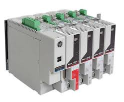
There are a few reasons I wanted to use these. First is that Rockwell opened up the interface for the Ethernet drives to allow you to enter the motor data manually if you choose. This isn't recommended and Rockwell won't support you, but it does open the door to using 3rd party motors which just was not possible with the SERCOS series of drives.
Second is that the Ethernet drives have additional testing and diagnostics. I can run a commutation test to determine the correct commutation offset to program into the motor, and I can collect a ton of runtime data from the motor and plot it on my laptop. There are seriously hundreds of parameters and data tags you can look at. The commutation test reported a required offset of 92.5 degrees which is very close to the 90 degrees reported by the Ultra 3000 earlier in this project.
The drives I have are 480V units which I obviously don't have at home. I currently have them powered at 120V and the motor is rated for 200V. This is really not ideal, but I can disable the undervoltage protection on the drive by placing them in "demo mode". I can also disable the motor voltage mismatch fault which would prevent me from running the 200V motor with the 480V drive.
With these features activated, I entered the motor data in the nameplate entry field and was able to pass all of the hookup tests and tune the motor. It runs beautifully! I let it run for hours with zero hiccups. These drives are really high end and the motor is almost silent when running. All the other drives I have used have a high pitched whine due to the current switching frequency. I wish I had access to 4 of these in the 240V flavor for use at home, but that isn't going to happen
My next step is to get these drives to run the motor with the data coming from the CMF file I wrote. If that works then there should be absolutely no reason why I can't run it on the Kinetix 2000 or Ultra 3000 over SERCOS.
I'll try to hook the belt up to the Z axis ballscrew and post a video of the robot moving under control!
- Joined
- Mar 26, 2018
- Messages
- 2,725
I've been working some long shifts at work and haven't had any shop time. Managed to get a few hours yesterday to make some progress on the robot and wanted to share.
I'm fed up with trying to get this working with the Kinetix 2000 Sercos drives. I might revisit this again in the future. It should work, and it irks the heck out of me that I can't figure it out. I'm also trying to hunt down some newer ethernet drives, but for now, I don't have any.
It dawned on me a week ago another way I can approach this. If you remember, I had the motor working perfectly with an Ultra 3000 operating as a standalone drive, but when I tried to run the motor on the exact same drive over Sercos, it wouldn't work. Well I remembered a way I can get it to work with the standalone drive and the PLC running the robot math. Rockwell makes a servo interface module for the PLC called the 1756-M02AE. It is a 2 axis analog servo module designed for making Rockwell PLC's talk with any generic (and old) servo equipment. I happen to have 2 of these (for a total of 4 axis) that I can hook up.
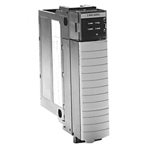
The module works by sending an analog torque command to the servo. Traditionally, the servo drive would close the torque, velocity, and position control loops, however with this module, you dumb down the drive by only letting it control the torque loop. The 1756-M02AE module is then responsible for the velocity and position control. The motor encoder is still connected to the servo drive, but only for commutation data. The encoder data is buffered by the servo drive and then passed to the 1756-M02AE module through a cable.
The benefit of this is pretty much guaranteed success (watch this comment bite me in the you know what). The design is simple and rugged. The downside is a total loss of data from the drive and susceptibility to noise on the analog command line. The Sercos drives were able to transmit diagnostic data over the optical fiber, and I will lose all of that data.
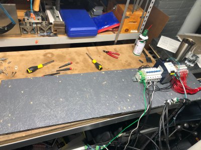
Here was my controls rig before I started this new attempt.
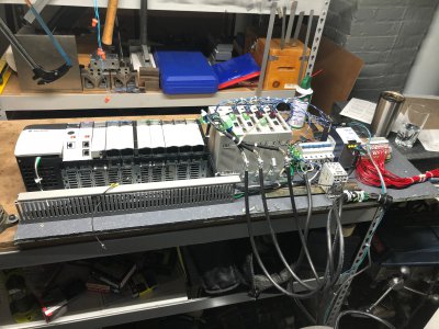
And gutted:
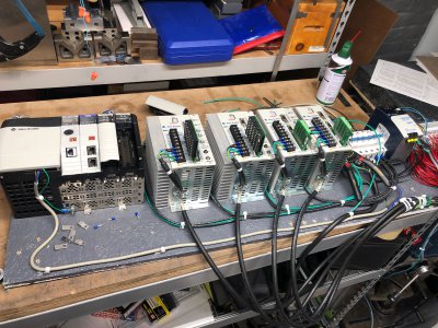
And with a 4 slot PLC rack and 4 drives. I don't have matching drives unfortunately, but for this project I can disable the SERCOS option module on the first two drives to use them as a stand alone unit, and I do not need to use any of the DeviceNet features on the 3rd drive. Ideally, I'd like to find 4 matching 500W basic drives like the one on the far right.
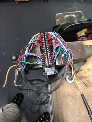
Here is the removable terminal block (RTB) for the analog servo module. It has quite a lot of wires going to it. One large bundle goes to each drive, and a smaller cable goes to the terminal blocks to read the homing sensor on each robot axis.
And all zipped up.
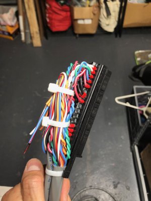
And installed on the servo module.
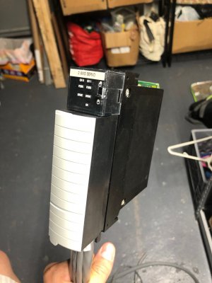
I ran out of time, but my next step is to test the Z axis under analog control. This will require setting up the program for these modules, and configuring the drive for analog torque reference. This is a couple hours of work there. If it works, then I can hook up the other 3 drives.
I also ordered the version B of my encoder interface circuit. This one will have all my changes integrated to the board. That should be in within a week. I'm really hoping that this works without edits needed.
I really wish that the Sercos drives worked out, but this should do the trick and provide good motor control.
I'm fed up with trying to get this working with the Kinetix 2000 Sercos drives. I might revisit this again in the future. It should work, and it irks the heck out of me that I can't figure it out. I'm also trying to hunt down some newer ethernet drives, but for now, I don't have any.
It dawned on me a week ago another way I can approach this. If you remember, I had the motor working perfectly with an Ultra 3000 operating as a standalone drive, but when I tried to run the motor on the exact same drive over Sercos, it wouldn't work. Well I remembered a way I can get it to work with the standalone drive and the PLC running the robot math. Rockwell makes a servo interface module for the PLC called the 1756-M02AE. It is a 2 axis analog servo module designed for making Rockwell PLC's talk with any generic (and old) servo equipment. I happen to have 2 of these (for a total of 4 axis) that I can hook up.

The module works by sending an analog torque command to the servo. Traditionally, the servo drive would close the torque, velocity, and position control loops, however with this module, you dumb down the drive by only letting it control the torque loop. The 1756-M02AE module is then responsible for the velocity and position control. The motor encoder is still connected to the servo drive, but only for commutation data. The encoder data is buffered by the servo drive and then passed to the 1756-M02AE module through a cable.
The benefit of this is pretty much guaranteed success (watch this comment bite me in the you know what). The design is simple and rugged. The downside is a total loss of data from the drive and susceptibility to noise on the analog command line. The Sercos drives were able to transmit diagnostic data over the optical fiber, and I will lose all of that data.
Here was my controls rig before I started this new attempt.

And gutted:

And with a 4 slot PLC rack and 4 drives. I don't have matching drives unfortunately, but for this project I can disable the SERCOS option module on the first two drives to use them as a stand alone unit, and I do not need to use any of the DeviceNet features on the 3rd drive. Ideally, I'd like to find 4 matching 500W basic drives like the one on the far right.

Here is the removable terminal block (RTB) for the analog servo module. It has quite a lot of wires going to it. One large bundle goes to each drive, and a smaller cable goes to the terminal blocks to read the homing sensor on each robot axis.

And all zipped up.

And installed on the servo module.

I ran out of time, but my next step is to test the Z axis under analog control. This will require setting up the program for these modules, and configuring the drive for analog torque reference. This is a couple hours of work there. If it works, then I can hook up the other 3 drives.
I also ordered the version B of my encoder interface circuit. This one will have all my changes integrated to the board. That should be in within a week. I'm really hoping that this works without edits needed.
I really wish that the Sercos drives worked out, but this should do the trick and provide good motor control.
Last edited:
- Joined
- Mar 26, 2018
- Messages
- 2,725
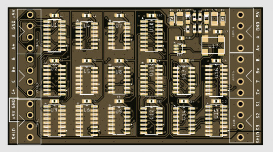
New circuits are in and I got a test unit assembled. I'm getting much quicker at the PCB assembly process, this one only took me about 2 hours to stencil the paste on, place the components, reflow, and clean. I'm pretty confident that this will work now, especially since the reworked board hasn't had a glitch since I put it together.
This board added the 3 chips in the second column from the left.
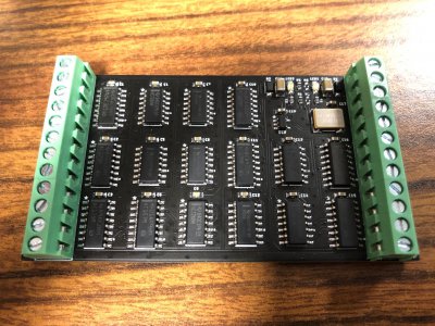
Next step is to make sure the motors work well with this board. From there I can test the Z axis motor under control of the analog interface card. If that works, then I can go through motor by motor and get them hooked up.
Hoping work slows up a bit so I can make some more progress on this.
-Mike
This board added the 3 chips in the second column from the left.

Next step is to make sure the motors work well with this board. From there I can test the Z axis motor under control of the analog interface card. If that works, then I can go through motor by motor and get them hooked up.
Hoping work slows up a bit so I can make some more progress on this.
-Mike
- Joined
- Mar 26, 2018
- Messages
- 2,725
Planned to spend an hour or two last night testing the new feedback board and analog control of the drives. First thing I needed to do was move the control board with all the drives back under the robot and connect the cables. I powered it on and everything started up fine. I noticed I forgot to hook up the brake leads from the Z axis motor to the 24V PSU.
I didn't want to go find my laptop and pull up the manuals, so with everything powered up, I plugged the wires into the PSU and the brake opened up. I wanted to make sure I got the polarity correct so I removed the wires and swapped them (expecting it to also open the brake or not do anything) and then plugged them into the power supply again.
It was at this moment I knew I screwed up... There was an orange flash from the base of the robot and the stench of burnt electronics. I tried reversing the wires back to the right way, but the brake wasn't working anymore.
Turns out I fried a trace off of the main breakout board in the base of the robot (EPSON SKP337). The robot assumes it is connected to a matching controller, so there is no reverse polarity protection built in. I assumed this board just passed the signals from the SCSI-68 connector which is where the signal cable plugs in, but there is a bit more going on there.
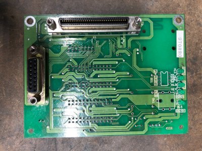
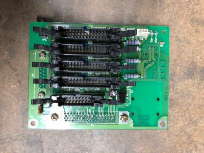
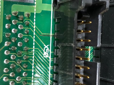
You can see the burnt trace near the top of this photo. It goes under all 5 of the black plastic connectors, so those will need to be removed and the trace cleaned up. There is a risk of the trace lifting off of the board and shorting pins on the bottom of the connector.
I spent two hours tracing out the PCB in the region where the trace failed and here is the schematic I was able to put together. What I did was connect 24V+ to terminal block 66 and DC COM to 67. This forward biased the diode VD1 which failed to a dead short as 10A @ 24V flowed from the power supply. The trace between SCSI pin 64 and VD1 is probably 10mil while the trace between VD1 and SCSI pin 66 is probably 50 mils. There was no fuse present so the trace between SCSI pin 64 and VD1 was the first thing to blow.
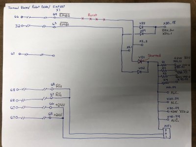
I *believe* that terminal 67 (SCSI 65, 66) is the +24V supply rail to the robot. That power is shared between the brake coils (only 1 present on this unit) and the optical/inductive homing sensors. I believe VD1 and VD2 are flyback diodes used to clamp the reverse voltage spike generated by the brake coil in the motors as they turn off and the magnetic field collapses.
I also think this board is probably shared between many different flavors of this robot. I have not pinned it out entirely, but it looks like there are places on the board for an 8 pin IC, a large switch of some kind, and a battery holder to maintain absolute encoder positioning during power cycles.
My plan is to remove all of the black plastic connectors with the hot air rework station I was using to solder the feedback boards. I'll clean it up with flux and solder wick and finally peel the damaged trace off of the board. From there, I can run a new wire to replace the trace and tape it to the surface of the board. The diode should be able to be replaced by any generic diode with a reverse standoff voltage greater than 24V and a response suitable for clamping coil surge.
I don't want to, but I should probably take the time to draw the rest of the circuit out so I have it for reference in the future. They did some goofy stuff here and I do need to understand it better.
I didn't want to go find my laptop and pull up the manuals, so with everything powered up, I plugged the wires into the PSU and the brake opened up. I wanted to make sure I got the polarity correct so I removed the wires and swapped them (expecting it to also open the brake or not do anything) and then plugged them into the power supply again.
It was at this moment I knew I screwed up... There was an orange flash from the base of the robot and the stench of burnt electronics. I tried reversing the wires back to the right way, but the brake wasn't working anymore.
Turns out I fried a trace off of the main breakout board in the base of the robot (EPSON SKP337). The robot assumes it is connected to a matching controller, so there is no reverse polarity protection built in. I assumed this board just passed the signals from the SCSI-68 connector which is where the signal cable plugs in, but there is a bit more going on there.


You can see the burnt trace near the top of this photo. It goes under all 5 of the black plastic connectors, so those will need to be removed and the trace cleaned up. There is a risk of the trace lifting off of the board and shorting pins on the bottom of the connector.

I spent two hours tracing out the PCB in the region where the trace failed and here is the schematic I was able to put together. What I did was connect 24V+ to terminal block 66 and DC COM to 67. This forward biased the diode VD1 which failed to a dead short as 10A @ 24V flowed from the power supply. The trace between SCSI pin 64 and VD1 is probably 10mil while the trace between VD1 and SCSI pin 66 is probably 50 mils. There was no fuse present so the trace between SCSI pin 64 and VD1 was the first thing to blow.

I *believe* that terminal 67 (SCSI 65, 66) is the +24V supply rail to the robot. That power is shared between the brake coils (only 1 present on this unit) and the optical/inductive homing sensors. I believe VD1 and VD2 are flyback diodes used to clamp the reverse voltage spike generated by the brake coil in the motors as they turn off and the magnetic field collapses.
I also think this board is probably shared between many different flavors of this robot. I have not pinned it out entirely, but it looks like there are places on the board for an 8 pin IC, a large switch of some kind, and a battery holder to maintain absolute encoder positioning during power cycles.
My plan is to remove all of the black plastic connectors with the hot air rework station I was using to solder the feedback boards. I'll clean it up with flux and solder wick and finally peel the damaged trace off of the board. From there, I can run a new wire to replace the trace and tape it to the surface of the board. The diode should be able to be replaced by any generic diode with a reverse standoff voltage greater than 24V and a response suitable for clamping coil surge.
I don't want to, but I should probably take the time to draw the rest of the circuit out so I have it for reference in the future. They did some goofy stuff here and I do need to understand it better.
- Joined
- Jan 2, 2014
- Messages
- 9,226
Does the track show continuity from end-to-end? (it looks like you've drawn enough of the circuit to know)
If so, I'd be tempted to just leave it.
You're right it looks darkened in that one area, but if it is not delaminating from the board you might create more problems by removing all those connectors. Is it noticeably burnt between connectors too? (say X50 and X40)
I doubt it could lift enough under the connectors to cause shorting.
-brino


