Mike's SCARA Robot

Bought the parts to complete the Version 2.0 board. Most of the parts are the same so I just needed to replace the components used on the test board and add a few extra.

I bought large DIP chips for the new components to be added to the PCB. My hope is to try to solder them up on a breadboard and rework the existing PCB to prove functionality before I order the Version 2.0 boards from China. This is going to be a bit of a nightmare to try to solder, but I'm going to at least try it.

I think I know what the issue is, but there are a few replies to my questions on All About Circuits that cast doubt if I fully understand the problem. Parts should be here by Friday so I will have something to work on for the weekend!.
 
The only (small) piece of advice I could add would be to add some "rework" room between the outside rows of logic devices and the connectors. If you find that you need to add one jumper to one of those device pins you'll have a hard time getting a soldering iron in there to do it.

I'm pretty sure that if you never made this comment, my board would have worked on the first try! (Just kidding of course!). I'm not looking forward to having to rework the board. Of course it is on the chips right next to the terminal blocks too!!!!!
 
Spend some time last week and this weekend reworking the PCB to upgrade the Version 1.0 board to a Version 2.0. As a recap, my original PCB did correctly decode the signals coming from the motors on the robot, however it was prone to glitches where the outputs would flicker on and off sporadically.

I did a lot of research and theorized that the issues were caused by small timing variations when bringing 3 parallel signals and sampling them into clocked memory chips (Flip-flops). Sometimes, a signal might transition a bit more slowly than the other 2 signals and would fail to get sampled into the memory until the next clock cycle. This would cause corrupted data to be presented to the circuit for one clock cycle and caused further issues in the signal decoding and output memory sections of the circuit.

My solution was to modify the input sampling circuitry by adding: (1) 4 Channel 2-Input XNOR gate, (1) 3 Channel 3-Input AND gate, and (1) 4 Channel 2:1 multiplexer. These chips work together to detect when an input has changed state and prevent that sample from entering the circuit. Only when 2 successive input readings agree can the outputs of the circuit be updated

While the plan is to create a Version 2.0 PCB with 3 additional SOIC (Small Outline Integrated Circuit) chips, I wanted to validate the design on the existing PCB. To do so, I bought extra of the new chips in DIP (Dual In-Line Package) packaging, a larger through hole variant of the component. These are the classic integrated circuits you see on old electronics. I soldered up a small breadboard with these components and various jumper wires to make the interconnections.
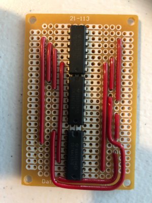
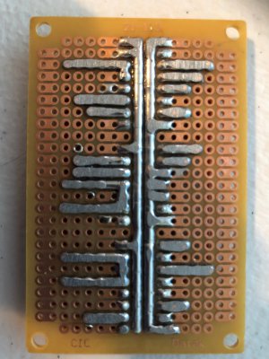
image019.jpg
image020.jpg

I then removed the motor side terminal blocks and the U2 chip from my functioning test board. I identified 3 traces on the Version 1 board that needed to be cut before patching in the new circuitry. The traces are 10 thou wide and 1.4 thou thick. I used a heavy duty X-acto knife to dig out the copper and make a decent sized air gap. You can see the cut traces between U2 pins 2 and 5, U2 pins 10 and 13, and U3 pins 2 and 5. When I was done, I soldered U2 back in place.
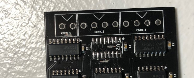
image022 - Copy (2).jpg

All I had on hand was some 24 Ga solid core hookup wire so I used that to solder to each IC pin that needed a splice connection. Care had to be taken to avoid lifting the leg of the IC from the pad on the PCB as the solder cooled. 12 wires were needed in total (+ 2 power connections)
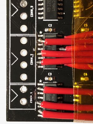
image024.jpg
The wires were secured to the board with Kapton tape to prevent strain on the connection, and the wires were labeled according to the schematic.
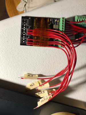
image025.jpg

And the wires were terminated on the breadboard.
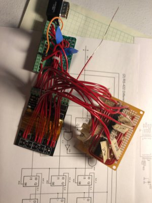
image026.jpg

Wire by wire, the enitre first half of the circuit was checked, first against the schematic, and second against the simulation functional diagram (assuming the schematic was wrong). I didn't find a single short or missed connection!
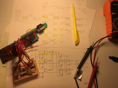
image027.jpg

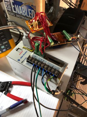
I then set everything up on my bench by the robot and got to work bench testing the new circuit, just as I did with the original one. Scope channels A, B, and C measured the input channels A, B, and C, while the 4th probe "D" was used to test various locations on the PCB. The robot Z axis motor was hooked up to this board and power was jumpered to allow the board to be used without the servo drive attached.
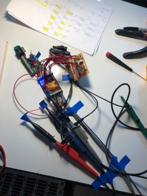
image028.jpg

Here is another shot of the work area.
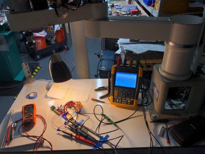
image030.jpg

And the results! First and foremost, the signals still come out of the board which is great news because my changes could have broken the entire thing. And second, since the addition of this circuitry, I have not seen a single glitch on the output! Everything looks very clean and I was able to verify that all channels output the correct waveform and transition at the appropriate times!
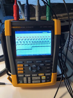
image029.jpg

When I got done building this, I had perhaps 30% confidence that I had identified the root cause of the problems and corrected it. I am so thrilled that it worked out. My next steps are to install the reworked PCB on the drive and try to get the commutation corrected and a motor running. When that is done, I will order the new PCBs which have already been designed.

Two interesting things... With the glitches removed from the output signals, I can now successfully detect the index/marker signal (Z) when the board is connected to the servo drive. I had not been able to pass that test previously due to all the glitches triggering a premature completion of the test. The second is I observed a startup sequence on the encoder when it was first powered on. It didn't dawn on me what I was seeing so I didn't investigate further, but there was some brief signal on channels A, B, & C and the output S1 turned on (all without the motor moving). This is great news since it means the motor/custom PCB are able to transmit the correct data before the drive boots up. Then I don't have to worry about the halls state being invalid before the motor is moved. This also means the PCB must be powered on at the exact same time (or earlier) as the encoder. This forces me to power the logic circuit from the same external supply as the encoders (jumper on the PCB) or to install a time delay relay in front of the 5V external supply to delay it until the drives have powered on and are supplying 5V out to the encoder ports.

Still making progress! Thanks to everyone for hanging in there with me!

-Mike
 
I can't speak for anyone else, but I am fascinated by this build and "on the edge of my seat" :)
+1, totally blown away by what Mike is doing here. He must have gone to the Einstein/Tesla school of Engineering!

Bruce

Thanks so much guys! Truth be told I didn't really study this stuff in college other than two courses on introductory electronics. I mostly focused on control theory which I have barely used since then. I do just love to dive into stuff and try to learn what I need. Always been very interested in robotics and I'm willing to put in the effort to learn anything I need to get this working.

I really appreciate the involvement of everyone on this project. It often gives me the kick I need to keep going when I get stuck. I feel like I am letting people down when I am not making progress.
 
Even if you think you are not making progress (as far as getting positive results), in science, negative results are more powerful than positive ones. It only takes ONE negative result to disprove a theory, while even a million positive test results are suspect because the 1,000,001'th test could be a negative result.

So if you're learning from your mistakes (and it most certainly appears you are), it's all good!
 
Spent an hour on the robot last night working on commutation. Still no luck, but I have another coworker who is willing to give me a hand and see if we can get this working!

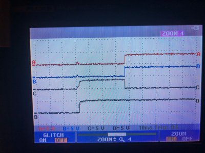
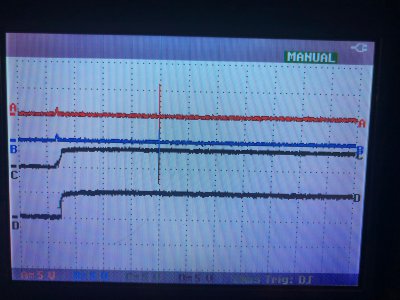
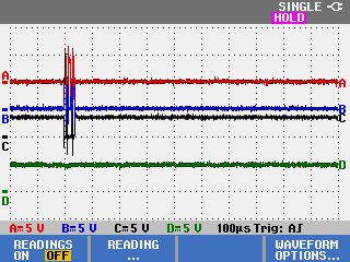
What I did figure out was the encoder startup sequence. For this test, the encoder and converter board were powered by the same 5V supply and the scope was powered on before the board and the trigger armed. When I turned on the power, the scope captured the first moments of the signals. Here is what I found (sorry some are phone pics). The traces A, B, & C are the outputs from the encoder A, B, C respectively. Channel D is scoping the S2 commutation output from my converter board.

When power is applied to the encoder, there is a small blip on channels A and B. Channel C slowly rises and then 40-50ms later, the signals crisply snap to their operating states.

image031.jpg

If you watch it a bit longer, you see this sharp notch in the A,B, & C signals.

image033.jpg

Here is a zoomed in view of that notch.

IMAGE059.jpg

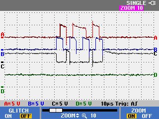
And Zoomed in even more! What we see here is the encoder puts out 7 forward and 7 reverse counts in rapid succession. This all happens with absolutely no motion of the motor shaft, it is a purely digitally controlled startup "message" that the encoder sends to "preload" the correct state into the receiving circuit.

I've been worried this whole time about how the drive will know the commutation state at startup without the motor moving at least 3 counts. It seems like Yaskawa knew this problem too and this is how they managed to solve it. This works perfectly for my PCB design as well and it sets the appropriate outputs just a couple milliseconds after the encoder powers on.

This startup message loads the NAND pattern into my detection circuit and sets the outputs S1 LOW, S2 HIGH, S3 LOW, Z LOW.

IMAGE055.jpg

This does confirm that my PCB needs to be powered on at the same time as the encoder in order to detect this startup message.

Pretty darn cool!
 
Last edited:
Just don't send this thing through the time displacement equipment..
Robert
 
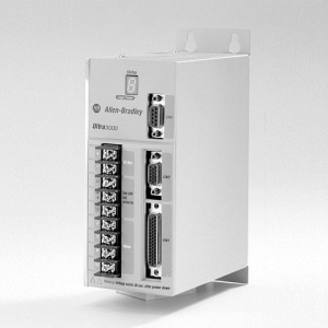
Had a pretty big breakthrough today! My coworker recommended trying to run the motor on an Ultra 3000 servo drive instead of the Kinetix 2000 I have been using. This is an older drive but is absolutely bulletproof. I am running 6 of them on my CNC'd G0704. The drive operates completely standalone from a PLC controller and is programmed by a serial port on the front.

1595714147258.png

The configuration software (Ultraware) allows you to create custom files for 3rd party motors and runs a much simpler mathematical model of the motor compared to the Kinetix 2000. This means less motor parameters. Unfortunately without the PLC, I cannot do the kinematic transforms needed to run the robot, but this at least lets me test the motor.

For the first test, I created a custom motor with the correct parameters and told the drive to do self sensing commutation. I wired the motor directly to the drive without my custom feedback adapter board. This was initially unsuccessful, however once I wired the motor leads in reverse (WVU), the algorithm was able to power up the motor, force the shaft to a pole location and measure the commutation angle. From there, the commutation angle is measured as an incremental distance from the starting location. The motor was completely responsive and ran without problems, including some very aggressive indexing moves at the 4500rpm limit of the motor.

In the next test, I added my adapter board and changed the motor file to use hall effect sinusoidal commutation. The Ultra 3000 features a "Commutation Test" which runs the motor open loop and suggests changes to correct wiring and indicates the correct commutation offset. When this test was run, it told me to wire the hall effect feedback signals from my adapter board as S2, S1, S3 and apply a 90 degree commutation offset. When these wiring changes and configuration changes were made, the motor ran perfectly!

IMG_9369.jpg

So here is what I learned:
  • The motor power wiring should be W-V-U
  • The hall effect feedback wiring should be S2-S1-S3
  • The motor works
  • The encoder works
  • The feedback adapter circuit (and rework) works perfectly
  • The correct commutation offset is 90 degrees
With this info, there is no reason the Kinetix 2000 shouldn't work! If I keep having issues, I can hook up a different Ultra 3000 SE which is enabled to talk over the SERCOS fiber optic ring and try to run the motor from that drive through the PLC. This will potentially have different results since it runs with the CMF file rather than the configuration I used for this drive. It also runs different firmware so it could behave differently.

View attachment 61738684628__821B0D81-290C-4C19-BF7E-713506EDC47A.MOV
 
Last edited:
Back
Top