Mike's SCARA Robot

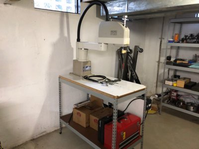
I moved late last year and haven't had a chance to work in the shop much at all. Finally got the SCARA robot set up on the table again at the new house, and I have an electrician coming next week to set up power.

One nice thing is that the ceiling is slightly higher in this house so the cable bundle can move freely without striking any ductwork which really increases the working area of the robot.

image215.jpg

I still plan to try out the idea of controlling this from CNC software but just need to find the time.
 
We've got a SCARA robot with controllers that is about to be scrapped. Offered free if you pick up shipping costs.
Robot is like new. Saw your thread and thought you might be interested.

Please contact us as soon as possible - timing is tight.

N&R Scientific - Palisades Park, NJ
 
We've got a SCARA robot with controllers that is about to be scrapped. Offered free if you pick up shipping costs.
Robot is like new. Saw your thread and thought you might be interested.

Please contact us as soon as possible - timing is tight.

N&R Scientific - Palisades Park, NJ
Private massaged you. Thanks for reaching out!
 
Wow blown away by all the effort you put into this project. I just read the whole thread. I found this site googling info for the yaskawa servos on my cartesian epson robot. If I end up needing to replace the drives your reverse engineering will save me so much time. Right now i'm having trouble finding the pinouts for the cacr drives. Ideally, I want to keep the drives and convert them to step/ dir input. The drives resemble the comercially available yaskawa drives but the connectors are completely different from any info I could find online.
 
Wow blown away by all the effort you put into this project. I just read the whole thread. I found this site googling info for the yaskawa servos on my cartesian epson robot. If I end up needing to replace the drives your reverse engineering will save me so much time. Right now i'm having trouble finding the pinouts for the cacr drives. Ideally, I want to keep the drives and convert them to step/ dir input. The drives resemble the comercially available yaskawa drives but the connectors are completely different from any info I could find online.
Thanks so much! I love these deep dive projects.

I’m not familiar with anything on the drive side of the robot since mine did not come with a drive. Converting a drive to step/dir if it was not designed for that control mode might be very tricky to do.

If you ever need some of the feedback converter boards I designed, just let me know. We can place an order to have a batch made up (they are pretty cheap) and you’d have to populate the board. They are surface mount components, but I picked big enough ones that it is pretty reasonable to assemble by hand and solder with a cheap reflow gun or toaster oven.

Share some pictures of your project - I’d be interested to see.
 
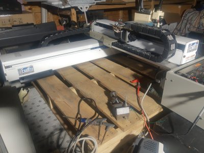
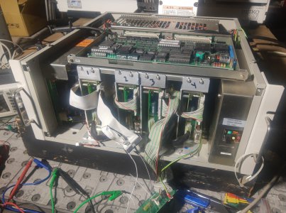
Finally had some time to get back to the robot.

I was able to get a 32 bit laptop from a friend that runs the old spel programing software. Everything seems to work on the machine. Jogging in the software was easy to figure out. I still need to learn to write an actual program. I was able to use a IDE floppy ribbon in place of the factory servo drive cable which allowed me to probe the pins while running. I new right away when I saw -5v hope for a pulse/dir input was probably dashed. Probing around I have figured out the power +24, +5, -5, the drive enable, and the motor encoder pins go to the robot MPU then straight thru to the drives. Whats handy is the individual drives can be "ignored" by the MPU with some DIP switches. Also, the drives can individually be un-enabled from the jog/ program software window to allow manually positioning the axis. This was super helpful to determine the pinouts.

Couple of questions:

Is this project worthy of a new thread? It may go months between updates. The goal is using the robot for a DIY plasma table.

Second, Anyone familiar with velocity controlled servos? From what I can tell so far the drives only command the speed of the motor. The robot processor does the control loop. When the motor drive is enabled (and the MPU is set to ignore it) the servo is totally limp. Turning the motor by hand doesn't seem to fualt the drive. Which makes sense considering the software has a function to allow the axis to be moved manually for programing. This means (i think) the drive does no pulse counting or position traking. Does this make sense? I was able to enable a drive and use a pot to send voltage to the velocity input and move the axis in both directions. Moving the pot very rapidly cuased the drive to fualt. Unfortunately, I couldn't find what drive pin output the fault becuase the MPU killed power to 24v, 5 and -5v not just the buss rail.

Next is to write an actual program. Probably just X moving back and forth 20' or so. In jog mode the max travel speed is limited to 5%. I need to move an axis close to max speed to measure what the max command voltage is going to the drive. Also hope the figure out if the 5% limit is fully implemented in the MPU or the servo drive itself. Some of the yaskawa drive manuals (for different drives, can't find info on the ones in the robot) have speed limit settings that can be set by taking pins H or L.

Thanks for the offer on the converter boards. Still hoping to use the OEM drives. Looks like I will have to make a pulse counter and pid controller for each axis.
 

Attachments

  • IMG_20240107_131246819.jpg
    IMG_20240107_131246819.jpg
    447.7 KB · Views: 8
  • IMG_20240107_131253417.jpg
    IMG_20240107_131253417.jpg
    521.7 KB · Views: 8
Finally had some time to get back to the robot.

I was able to get a 32 bit laptop from a friend that runs the old spel programing software. Everything seems to work on the machine. Jogging in the software was easy to figure out. I still need to learn to write an actual program. I was able to use a IDE floppy ribbon in place of the factory servo drive cable which allowed me to probe the pins while running. I new right away when I saw -5v hope for a pulse/dir input was probably dashed. Probing around I have figured out the power +24, +5, -5, the drive enable, and the motor encoder pins go to the robot MPU then straight thru to the drives. Whats handy is the individual drives can be "ignored" by the MPU with some DIP switches. Also, the drives can individually be un-enabled from the jog/ program software window to allow manually positioning the axis. This was super helpful to determine the pinouts.

Couple of questions:

Is this project worthy of a new thread? It may go months between updates. The goal is using the robot for a DIY plasma table.

Second, Anyone familiar with velocity controlled servos? From what I can tell so far the drives only command the speed of the motor. The robot processor does the control loop. When the motor drive is enabled (and the MPU is set to ignore it) the servo is totally limp. Turning the motor by hand doesn't seem to fualt the drive. Which makes sense considering the software has a function to allow the axis to be moved manually for programing. This means (i think) the drive does no pulse counting or position traking. Does this make sense? I was able to enable a drive and use a pot to send voltage to the velocity input and move the axis in both directions. Moving the pot very rapidly cuased the drive to fualt. Unfortunately, I couldn't find what drive pin output the fault becuase the MPU killed power to 24v, 5 and -5v not just the buss rail.

Next is to write an actual program. Probably just X moving back and forth 20' or so. In jog mode the max travel speed is limited to 5%. I need to move an axis close to max speed to measure what the max command voltage is going to the drive. Also hope the figure out if the 5% limit is fully implemented in the MPU or the servo drive itself. Some of the yaskawa drive manuals (for different drives, can't find info on the ones in the robot) have speed limit settings that can be set by taking pins H or L.

Thanks for the offer on the converter boards. Still hoping to use the OEM drives. Looks like I will have to make a pulse counter and pid controller for each axis.
Very cool you have the controller.

So looking back in history to the mid 90's when this equipment was designed, most servo drives we simple torque or velocity amplifiers. Only premium standalone servos were full position loop capable. The encoder would be wired to a motion controller or motherboard for the robot which would close the position and usually also the velocity loops and provide an analog reference to the servo amplifier to generate the torque signal and voltage waveform. My other robot from the same timeframe (Denso 6 axis) has 6 torque servo amplifiers with all the control being done by the controller motherboard.

You may find it easier to control this robot with a generic servo drive that accepts Step/Dir signals and use the feedback cards I designed to interface to the encoders. The hardest part is collecting the motor performance data if they are different motors from the ones I have already collected that info for. If you think it will be fun to design the motion control side doing the position and velocity loops, I think that is awesome. Be aware that you'll likely need to implement in hardware or FPGA to get acceptable performance. You'd want to close the velocity loop in the 250-500us range and the position loop no slower than 1-2ms. Modern motion control is done somewhere around the 32-64us for Torque, 64-128us for velocity, and 128us-1ms for position loop. This would be very demanding to handle in software alone. Most if not all servo drives I know run the control in FPGA.

One other idea would be to see if there is a way to stream commands to the old robot controller. My Denso has a way to stream position commands via RS232 into the controller and the robot will follow. This would allow you to implement a bridge between CNC software (like Mach4) and the robot by sending position commands over at a regular interval. Not easy, but perhaps easier than scratch building a robot controller. There are benefits to reusing the original robot controller as intended.

I'd definitely follow your progress if you'd like to start your own thread!

Mike
 
Back
Top