Project update time!
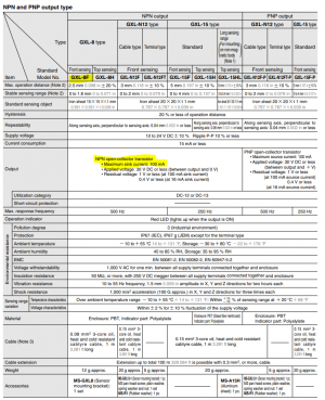
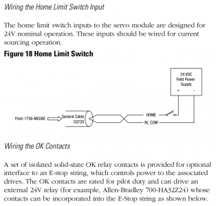
Z Axis Homing is completed and functional. My addition of the external 2000 ohm 2W resistor worked well and gave me a respectable voltage of 19V when ON and 2V when OFF. Not ideal, but sufficiently above and below the noise margins on that input. I configured the servo module to use a Normally Closed homing sensor. I then added homing to the simple program I wrote before so the Z axis fully retracts before starting movement. I also rewrote the code to use absolute positions instead of incremental distances. Here is a short video of that in operation. (I am having trouble with the video sizing. Something with the HM interface. If you view fullscreen, the resolution and size should be better)
View attachment IMG_9669.MOV
The axis drives towards the switch at a medium speed. When the sensor is triggered (red LED comes on), the motor stops and reverses off of the switch at 1/8 of the initial speed. When the home sensor turns off, that position is recorded as home and the program begin a cyclic up and down movement.
Amusingly, you can see my cat chilling on my workbench in the background.
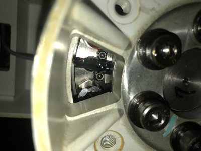
T1, T2, T4 Homing is my next major hurdle. I ended up starting a post on All About Circuits to try to get some help on this. Unlike the Z axis, which uses an inductive proximity sensor, the remaining 3 joints use an Omron EE-SV3 "Photomicrosensor (Transmissive)" with a fiberglass "code wheel" to trigger it. I'm pretty sure I have the EE-SV3-B model. Here is the link the the datasheet:
https://omronfs.omron.com/en_US/ecb/products/pdf/en-ee_sv3.pdf
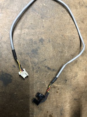
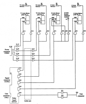
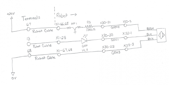
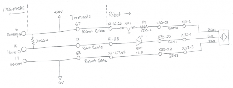
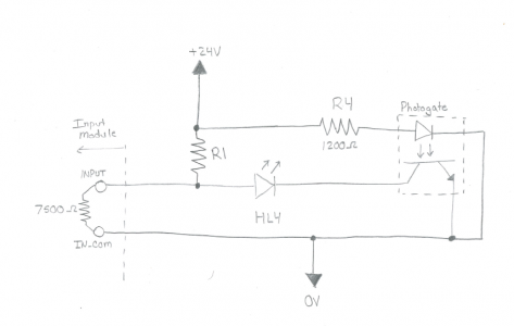
Here is a schematic of the sensor on U axis.
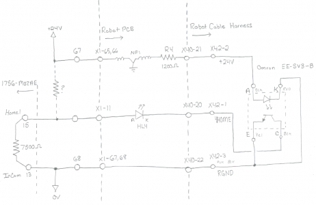
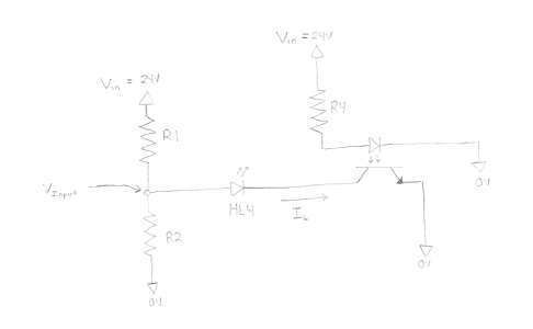
This sensor is configured to work similarly to the proximity sensor in that it pulls the input down to 0V, however it differs in that when it is ON (nothing sitting between the gate), it only sinks 6mA (while the proximity sensor could sink up to 100mA). This means it is unable to pull the input below the 8.5V requirement when the input is pulled up by the 2000 ohm external resistor.
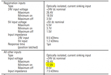
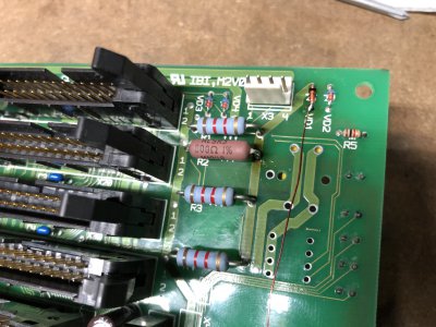
I did the math and it turns out there is no value for the external resistor which satisfies both the input high >17V and input low <8.5V requirement. I'll save the gory details, but what I ended up needing to do is change out a resistor on the robot's internal PCB from 1200 ohm to 800 ohm. This allows more current to pass through the photogate emitter and also allow it to sink more current on the phototransistor. By adding the 2000 ohm external resistor and swapping in an 800 ohm resistor, I *should* be able to get 6V when the input is low and 19V when it is high. This should be acceptable.
I purchased some 800 ohm 3W resistors from Digikey at $2 each. I didn't want to modify the robot at all, but this is a small change to allow me to use the analog servo interface module that I have. These should arrive tonight.
Here is a simplified version of the schematic. I will be installing R1 externally with a value of 2000 ohms. I will be removing R4 from the robot PCB and replacing it with an 800 ohm.
 DIN Rail Components
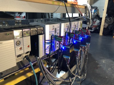
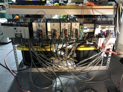
Here's a picture of where the DIN rail wiring stands.
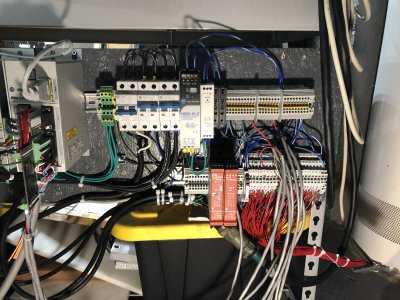
Starting at the top left, I have a couple of terminal blocks for connecting PE grounds. Then there is a 20A main breaker (shares power to the other two breakers), a 6A breaker for the PLC and DC power, and another 20A breaker just for the drives. There 6A breaker feeds the 24V 3.5A supply and the 5V 2A supply. Each supply passes through a fuse and gets distributed across the terminal blocks on the top.
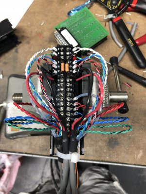
The bottom row has some spare terminal blocks for the safety wiring, a dual channel input safety relay and an expansion module. Then there are a few terminal blocks and a slim SPDT relay for the Z axis break. Finally there are 68 terminals connected to the robot SIGNAL cable.
I don't love how messy this is, but hopefully I can clean it up if I put this in an enclosure at some point.
I started the
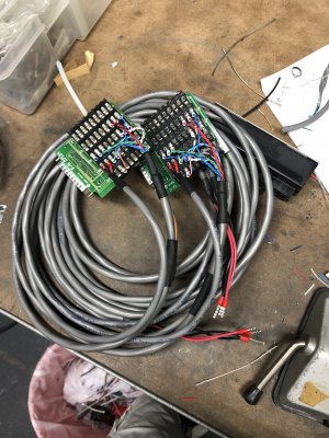
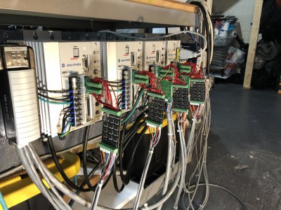
T1 & T2 Drive Wiring. I hooked up cable to the remaining two feedback adapter boards. I will go back and clean up the Z axis wiring as well - it is messy since it was the first one I worked on.
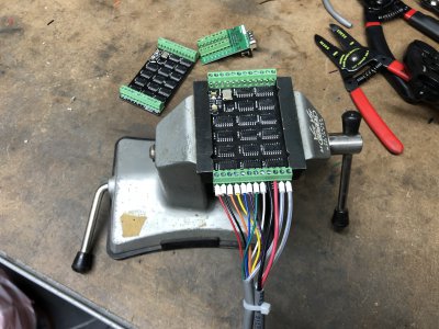
Looks pretty clean actually!
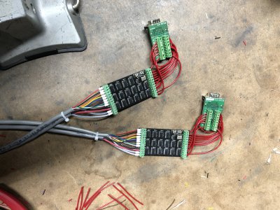
All 4 installed!
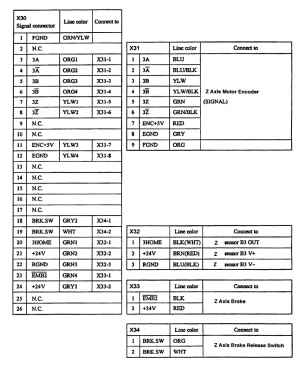
Terminal Block Pinout
I finally completed the mapping between my terminal block numbering and the SIGNAL number in the manual for the robot. They zig-zagged around the connector while I counted straight across. I think I followed industry standard - and I'm sticking to that story.
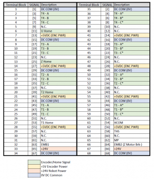
This will be very helpful to have. Not entirely sure what the signals HCOM, EMB1, and THS do yet.
Hoping to get the homing switches, T1 & T2 motor wiring, and the analog interface to T1 & T2 done soon. I see the light at the end of the tunnel for work, so I hopefully I will have a bit more time soon.
-Mike

