-
Welcome back Guest! Did you know you can mentor other members here at H-M? If not, please check out our Relaunch of Hobby Machinist Mentoring Program!
You are using an out of date browser. It may not display this or other websites correctly.
You should upgrade or use an alternative browser.
You should upgrade or use an alternative browser.
Clausing 5418 Lathe
- Thread starter Rick_B
- Start date
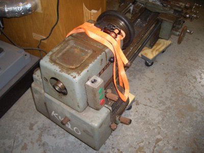
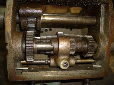
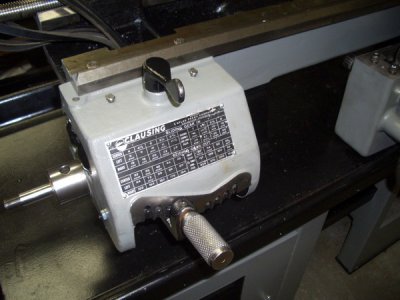
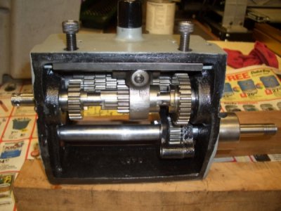
Some more progress - I finally got the gear box back together - let's just say I had a lot of practice putting together and taking apart while I figured out that jig saw puzzle  . I don't have a lot of before pictures but there are a few - followed by the after.
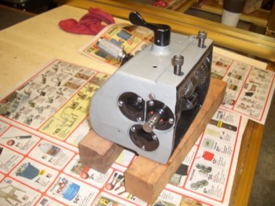
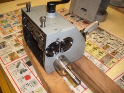
I moved on to the head stock - and am slowly sneaking up on a few problems I initially put aside so some questions will likely be coming.
Rick
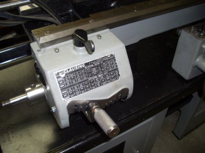
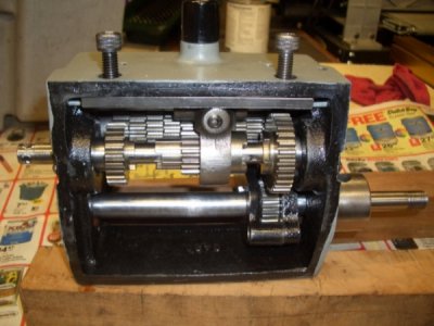
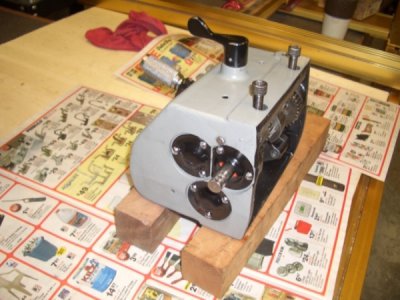
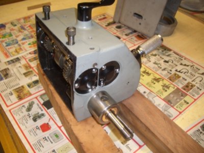


I moved on to the head stock - and am slowly sneaking up on a few problems I initially put aside so some questions will likely be coming.
Rick


I started out this morning with three disassembly problems - hoping to solve at least one of them. I was struggling with getting the large gear on the reversing mechanism off - that just required a little soaking in kroil and the courage to use some force with the press so that came right apart. The second problem was the sliding gear assembly - the nut holding the gear in place didn't want to loosen and there wasn't a good way to hold the stud. Again kroil, the vise on the bridgeport and some extra force loosened that nut. Then a press easily got the gear off the stud. Finally I figured out how to get the sliding stud out of the main stud.
I brought up the final problem early is this thread - getting the collet chuck back plate disengaged from the spindle L00 lock ring. I ended up bolting a 1/4 flat bar to the back plate and clamping that bar in a vise. Then a spanner wrench and a big hammer resulted in loosening the lock ring.
So its been a pretty successful day - now I can move on to cleaning up the spindle pieces and parts and getting that back together. All of the gear train/reversing gear parts are cleaned and ready to go - just waiting for some paint to dry. Also all of the covers and guards have been painted.
I'm expecting some additional problems to rise up when I get into the saddle/compound.
Rick
OK - so I'm dry fitting all of the gear train/reversing gears/covers and discovered that the rear guard on the gear box doesn't line up with the holes.This is basically a flat piece that bolts to the lower left side of the gear box and the head stock. Before I did my normal "just open the holes a bit snd get them to fit" I stepped back and looked at the schematic again. It appears there is a shim between the gear box and the bottom of the bed which would effectively drop the gear box allowing the holes to line up. The problem is I either lot that shim or didn't have one. I'm wondering if anybody might know the size of that shim? If I loosen the 3/8-16 allen head gear box screws one turn the holes line up - that tells me the shim needs to be roughly 1/16" - does that logic make sense?
Thanks
Rick
Thanks
Rick
Well I checked with Clausing - the shim is no longer available and no drawing is available. I found some 1/32 material n the shop and made a shim from that - as expected 1/32 was not enough so I doubled it up which allowed the holes to line up nicely.
In the process of solving this issue I also noticed that there was a 3/16 ga between this guard and where it bolts to the head stock. this was enough to allow the guard to flex when tightening the bolt. That made me nervous. I checked the parts diagram but there was no support block/shim in thst area. I decided it needed something so I found some 3/16 material in the shop with a clearance hole almost perfectly placed. So I hack sawed it to rough shape, dd some grinding and filing and painted it. It woks fine in terms of providing support behind the guard but I'm curious why that gap was there to brgin with. There is no adjustment that I can see - the head stock is locked in place via a locating pin and the gear box is locked in place by the mounting holes in the bed. I'm still not sure why the gap is there but until I discover a reason, I think the support block is the right way to go but am open to other's thoughts.
Rick
Based on information from several different sources - it appears the clausing spindle nose taper for the L00 spindle is a 4-12 MT. When I get home later todsay I'll see if Clausing has responded to my question yet as the final verification. Apparently Clausing offers this spindle sleeve (4-1/2 to 3 MT) but I have also found one from a member of another forum.
Rick
Rick
- Joined
- Nov 23, 2014
- Messages
- 2,606
Hi Rick,
I've read that the spindle is a 4 1/2 MT also. 99% sure I have a sleeve/center for mine and can take some measurements if you need them. I also have a MT 5-3 adapter, can check how well it fits in the Clausing. I figure the taper angle is what's critical (as long as the nose of an MT 5 doesn't stick out too far).
Bruce
- Joined
- Nov 23, 2014
- Messages
- 2,606
Hi Rick,
No way, no how to put a MT 5 center in the Clausing spindle. The small end of the MT 5 is larger than the large end of the MT 4 1/2 adapter. I read on some other threads that they are available from Clausing.
Bruce
No way, no how to put a MT 5 center in the Clausing spindle. The small end of the MT 5 is larger than the large end of the MT 4 1/2 adapter. I read on some other threads that they are available from Clausing.
Bruce
Bruce - thanks for the follow up. I actually found a 4-1/2 to 3 from a guy on the Clausing yahoo group. I'll let you know how that works. Clausing has not responded yet to my question but i think there has been enough verification that 4-1/2 is the correct taper.
Rick
Rick
Last edited by a moderator:

