-
Welcome back Guest! Did you know you can mentor other members here at H-M? If not, please check out our Relaunch of Hobby Machinist Mentoring Program!
- Forums
- THE PROJECTS AREA
- PROJECT OF THE DAY --- WHAT DID YOU DO IN YOUR SHOP TODAY?
- Project of the Day Mega-Thread Archives
You are using an out of date browser. It may not display this or other websites correctly.
You should upgrade or use an alternative browser.
You should upgrade or use an alternative browser.
2016 POTD Thread Archive
- Thread starter sanddan
- Start date
- Joined
- Nov 26, 2015
- Messages
- 36
This is not what I did today, but a project that was finished this month. It is the Beam Engine Mary. The plans came from the book of the same title by Tubal Cain.
Here is the YouTube link
Here is the YouTube link
- Joined
- Aug 29, 2013
- Messages
- 1,050
I machined a t-nut.
The finest I had was a worn 80 grit belt. This was the first one I turned and it was rough . In the middle I had a cutter fail leaving deep grooves . The belt took all that out .Logged on this morning and saw the pic just fine, don't know if there was a change or someone fixed but thanks.
by the way EB, I like your setup for polishing the barrel. Do you start with a large grit and keep working smaller grit, or just start with small and polish it.
I have two other barrels to spin that have a finish like this one has now. I have finer belts on order to make them look chrome. I'm afraid if I coat as is the finish when baked will lay down showing imperfection.
Sent from my SAMSUNG-SM-G900A using Tapatalk
Last edited:
- Joined
- Feb 8, 2014
- Messages
- 11,144
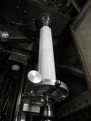
I got a little more done on the UHMW cylinder. It now has the flutes cut in it. These are not just slots, they are a very special shape and dimensions, a lot of design time went into them. It required 3 tool changes, and 5 separate operations for each slot to generate the shape. Their purpose is to pick up a rod that is between 4 and 10mm diameter, and only one rod, from a hopper. The rods are variable length up to 22 inches long, may be bent, and not of uniform diameter. It then delivers that rod to the next step in the process. And that's all I can tell you about that.
Since I am designing this project on the fly. the most efficient order of operation is not always possible. So back into the lathe to turn the bearing surface on one end. I already had center drilled the tailstock end, but the other end needs to be cut to length, so I pre-set the steady rest on center so I can face and center drill the other end when the time comes. Just thinking ahead a bit.....This time
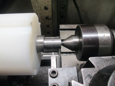
The snap ring groove was not planned, it should not have been needed. The front bearing mount is not symmetrical, and the internal flange was supposed to retain the bearing. But I built it backwards. So now I need to retain the bearing with a snap ring.
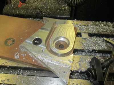
The front bearing mount. Made from a drop from another project. I have a shelf full of weird shaped pieces. This will go back on the shelf for the next project.
It was supposed to install this way, the bearing would have been captured between the the shaft flange and the bearing mount flange. But...........
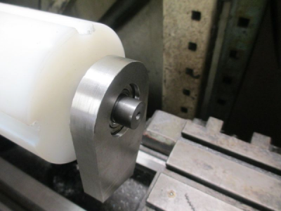
I pocketed the wrong side, I should have created a mirror image of the drawing and machined it from the other side. So this is the way it fits now. Functionally it will make no difference, but it's not the way I intended to design it.
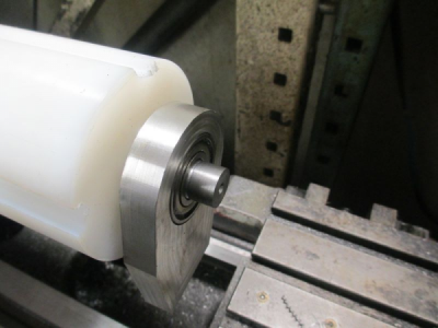

Since I am designing this project on the fly. the most efficient order of operation is not always possible. So back into the lathe to turn the bearing surface on one end. I already had center drilled the tailstock end, but the other end needs to be cut to length, so I pre-set the steady rest on center so I can face and center drill the other end when the time comes. Just thinking ahead a bit.....This time

The snap ring groove was not planned, it should not have been needed.

The front bearing mount. Made from a drop from another project. I have a shelf full of weird shaped pieces. This will go back on the shelf for the next project.

It was supposed to install this way, the bearing would have been captured between the the shaft flange and the bearing mount flange. But...........

I pocketed the wrong side, I should have created a mirror image of the drawing and machined it from the other side. So this is the way it fits now. Functionally it will make no difference, but it's not the way I intended to design it.

Last edited:
- Joined
- Aug 19, 2013
- Messages
- 764
Nice save.
- Joined
- Mar 25, 2013
- Messages
- 4,624
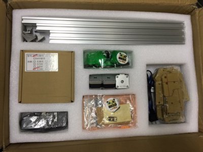
My first small steps into CNC - brought myself a laser engraver kit and it arrived today.
View attachment 134583
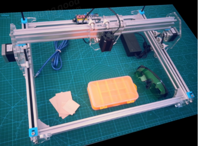
Should end up something like this once assembled.
View attachment 134584
Nice! I know nothing about these. How powerful is the laser and what can it engrave? Maybe this should be detailed in it's own thread?
Robert
- Joined
- Jun 26, 2014
- Messages
- 619
Nice! I know nothing about these. How powerful is the laser and what can it engrave? Maybe this should be detailed in it's own thread?
Robert
This one has a 2.5W laser and around an A3 operating envelope.
I had been slowly collecting components to build something similar with the intention of building an XY gantry and being able to swap between a laser, router and possibly a plasma cutter torch for the actual tool. But then I saw this kit on special so decided to go that way as this playing around with CNC is all new to me so is probably easier to start with something that should work first (and we can Frankenstein it later and expand).
http://www.banggood.com/2500mW-A3-3...re-CNC-Printer-Assembling-Kits-p-1003863.html
2.5W should allow me to engraver (well burn) wood and plastic and cut paper, foam and leather. Wont do anything to metal - you need to go to 50W CO2 lasers for that sort of thing, But I do hope to have some nice tool control foam inserts for my cabinet drawers in the my near future.
Will start a thread with the assembly and trial operation.
Last edited:


