-
Welcome back Guest! Did you know you can mentor other members here at H-M? If not, please check out our Relaunch of Hobby Machinist Mentoring Program!
You are using an out of date browser. It may not display this or other websites correctly.
You should upgrade or use an alternative browser.
You should upgrade or use an alternative browser.
The Journey Begins, PM Research #5.
- Thread starter EricB
- Start date
- Joined
- Feb 15, 2020
- Messages
- 399
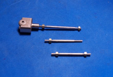
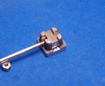
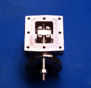
More little bits today. Made the glands for the piston and slide valve rods.
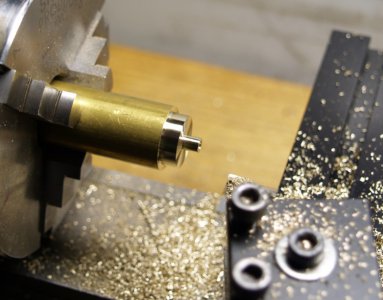
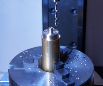
When I went to drill these two holes it never occurred to me to set the rotary table to zero first. So when I went to mill the final shape I had to figure the 15 degree angles from wherever it was. I guess I need a checklist.
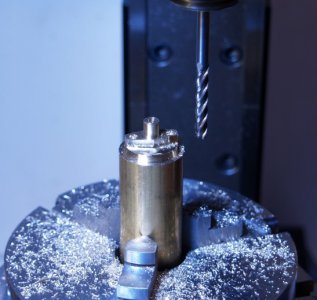
I did remember to add half the diameter of the end mill this time!
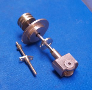
Now I can mark the hole locations on the inside head and the cylinder and drill those.
Progress.
Eric


When I went to drill these two holes it never occurred to me to set the rotary table to zero first. So when I went to mill the final shape I had to figure the 15 degree angles from wherever it was. I guess I need a checklist.

I did remember to add half the diameter of the end mill this time!

Now I can mark the hole locations on the inside head and the cylinder and drill those.
Progress.
Eric
Last edited:
- Joined
- Feb 15, 2020
- Messages
- 399
Fitted the glands to their associated parts and finished the inside head.
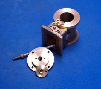
Still need to drill and tap the mounting holes in the cylinder. The locations for those are all picked up from other parts. I'll get to them eventually.
I should probably get me a center finder of some sort. Any suggestions?
Eric

Still need to drill and tap the mounting holes in the cylinder. The locations for those are all picked up from other parts. I'll get to them eventually.
I should probably get me a center finder of some sort. Any suggestions?
Eric
- Joined
- Jan 28, 2020
- Messages
- 197
Eric,
You asked, "I should probably get me a center finder of some sort. Any suggestions?"
Do you have a dial-test indicator? I came across a procedure in a book yesterday for using one to locate a center of a hole. I don't know whether a dial-test indicator counts as a center finder.
The book, Machine Tool Practices, 9th editon, by Richard Kibbe et al. also describes a coaxial dial indicator as being a "... useful tool for aligning a machine spindle with an existing hole or raised hub..."
Karl
- Joined
- Feb 15, 2020
- Messages
- 399
Eric,
You asked, "I should probably get me a center finder of some sort. Any suggestions?"
Do you have a dial-test indicator? I came across a procedure in a book yesterday for using one to locate a center of a hole. I don't know whether a dial-test indicator counts as a center finder.
The book, Machine Tool Practices, 9th editon, by Richard Kibbe et al. also describes a coaxial dial indicator as being a "... useful tool for aligning a machine spindle with an existing hole or raised hub..."
Karl
Hi Karl,
I have a Starrett Last Word that I use to center stock. I had never seen nor heard of a coaxial dial indicator. After watching a few videos it almost looks like cheating! Judging from the size I don't think I have the room in my little Sherline mill to use one anyway.
I was looking for a simple tool to center the spindle on a layout mark.
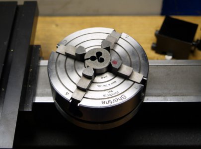
For the mounting holes in the bottom of my cylinder I ended up using a dead center in the spindle and a magnifying lens to find my initial position on the part which was centered in a 4 jaw chuck on the lathe and mounted on my rotary table. I did not have enough room to fit a drill chuck so I ended up using a 3/32" watchmakers WW collet to hold the drill. Not the best choice but it worked.
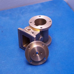
I think an extended mill column is in my future.
Eric
- Joined
- Jan 28, 2020
- Messages
- 197
Eric,
I wonder if anyone has tried using a dial test indicator with a stroboscope to emulate a coaxial dial indicator.
I have yet begun doing any layouts using the traditional tools. For years, my improvised method has been to do the layout to an image in Photoshop, print the image to scale onto paper, and paste the paper onto the part.
My Sherline 5400 vertical mill has the extended column, because I found Mike's [mikey] recommendations before I ordered it.
Karl
- Joined
- Feb 15, 2020
- Messages
- 399
Eric,
...
My Sherline 5400 vertical mill has the extended column, because I found Mike's [mikey] recommendations before I ordered it.
Karl
I purchased my mill used at a bargain price so it's standard stuff.
Anyway, back to my build. I used the same setup for the top head mounting holes. These are tapped 2-56. I used the top head to align the tap which was hand held in a pin vise. Easy.
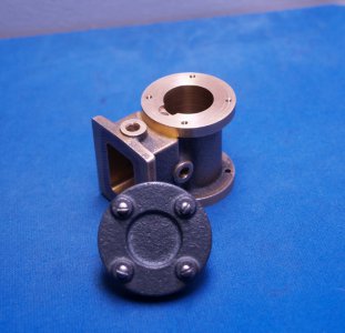
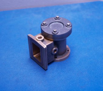
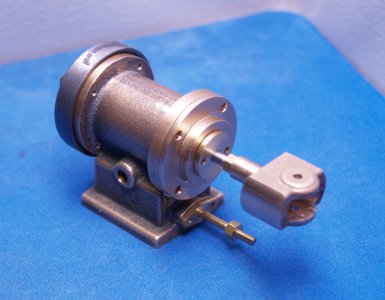
The head fits in any orientation so I guess I did ok.
It's a shame all this work is hidden once it's all assembled.
Eric
- Joined
- Feb 15, 2020
- Messages
- 399
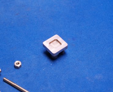
Today I did the valve chest cover and it's associated mounting holes in the cylinder.
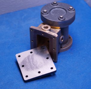
I used a fly cutter on the gasket surface but the casting reacted kind of odd. The outer edges seemed harder than the center and the cutter hollowed out the center. I rotated the part 90 degrees and took a heavier cut and it cleaned up. Odd.
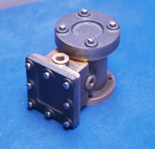
The plans say drill the holes 1/4" deep and tap 3/16". There wasn't enough material for that before I trued up the surface on the cylinder. The center top and bottom holes break into the steam inlet and the valve gland bores.
Eric

I used a fly cutter on the gasket surface but the casting reacted kind of odd. The outer edges seemed harder than the center and the cutter hollowed out the center. I rotated the part 90 degrees and took a heavier cut and it cleaned up. Odd.

The plans say drill the holes 1/4" deep and tap 3/16". There wasn't enough material for that before I trued up the surface on the cylinder. The center top and bottom holes break into the steam inlet and the valve gland bores.
Eric
- Joined
- Feb 15, 2020
- Messages
- 399
After staring at the drawings for months I decided to start on the eccentric.
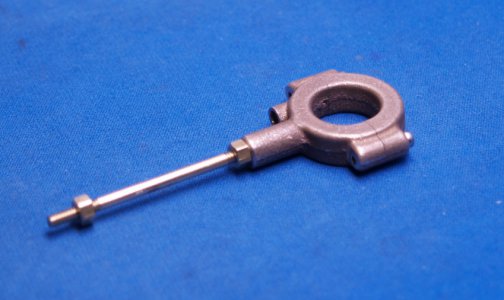
Used lots of different setups to hold it. Of course afterward I figured out I could have done most the work by holding it in a chuck by the push rod boss.
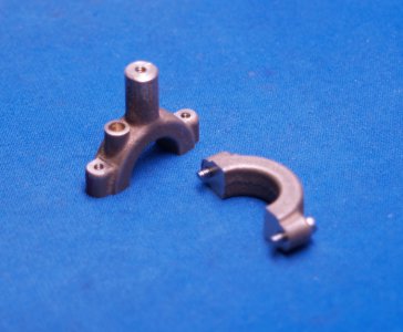
This was part of the same casting as the cross head, connected by the bosses for the push rods, so they needed to be separated first. What I should have done was part this from the cross head with its boss at the correct length and then finish the cross head. Instead I cut the cross head boss to length leaving this one to be done today.
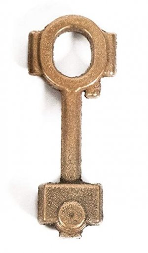
I still need to bore and groove the inside and face the sides.
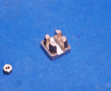
Started on the slide valve tonight too.
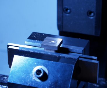
Eric

Used lots of different setups to hold it. Of course afterward I figured out I could have done most the work by holding it in a chuck by the push rod boss.

This was part of the same casting as the cross head, connected by the bosses for the push rods, so they needed to be separated first. What I should have done was part this from the cross head with its boss at the correct length and then finish the cross head. Instead I cut the cross head boss to length leaving this one to be done today.

I still need to bore and groove the inside and face the sides.
Started on the slide valve tonight too.

Eric
Last edited:

