-
Welcome back Guest! Did you know you can mentor other members here at H-M? If not, please check out our Relaunch of Hobby Machinist Mentoring Program!
You are using an out of date browser. It may not display this or other websites correctly.
You should upgrade or use an alternative browser.
You should upgrade or use an alternative browser.
The Journey Begins, PM Research #5.
- Thread starter EricB
- Start date
- Joined
- Feb 15, 2020
- Messages
- 399
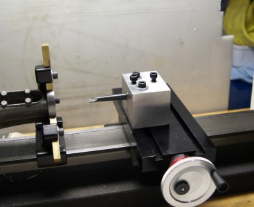
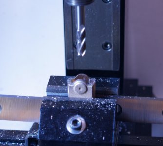
"Finished" the crankshaft today. Not perfect but usable. Here is the setup I used to turn down the journal on the mill. I had intended to do this on the lathe but there was too much vibration and the interrupted cut just blunted the tool. The end mill had no problems but it took a while with very light cuts.
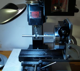
Thanks to my not carefully rechecking my setup the journal came out tapered so I put it on the lathe and squared it up with a file. It should still work.
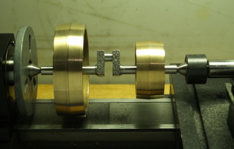
Test fit after turning the ends down to size.
Eric

Thanks to my not carefully rechecking my setup the journal came out tapered so I put it on the lathe and squared it up with a file. It should still work.

Test fit after turning the ends down to size.
Eric
Last edited:
- Joined
- Feb 15, 2020
- Messages
- 399
Still at it. Today's project started as an experiment to see if I could make a rigid setup with the engine frame centered on the spindle. The simple test was a light touch by the tip of a marker would leave marks on opposite corners of the casting with it spinning. It took several hours but I got there.
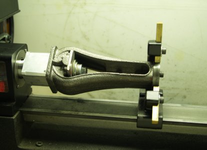
The opening in the bottom of the casting is a rough rectangle 1" x 1.25." I took the mandrel I used for the top cylinder head (#39 above), mounted it on the rotary table setup I used to finish the connecting rod journal on the crankshaft (#42 above), and shaped it to fit the opening with flat surfaces for the bottom of the frame to butt up against. Once I got it to a snug fit I took some light cuts on a couple of the flats to compensate for the problem I discovered (created) in #37 above. Once everything was centered and tight I was able to turn down the top end for the steady rest without any extra support at that end. It did chatter a bit though if I took too heavy a cut.
From there I went ahead and finished as much of the the top of the frame as I could without a long boring bar.
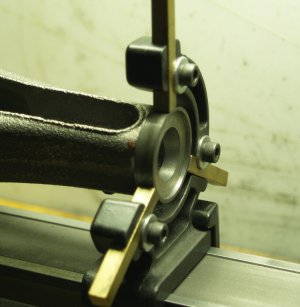
It will have to stay attached to the mandrel until I get it bored.
I saw a setup similar to this in Joe Martin's Tabletop Machining book. That was one of the reasons I decided on this kit in the first place. Mind you that engine was all bronze castings so I hope It will work with cast iron.
Also I figured out my setup mistake on the crankshaft and gave it another light touch on the mill to fix the tapered journal problem. Much better now but it's 0.025" under from the spec.
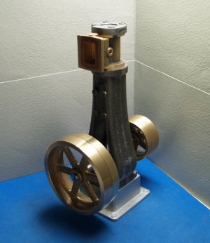
Here is a picture of some of the parts stacked up to get an idea of how it will eventually look.
Eric

The opening in the bottom of the casting is a rough rectangle 1" x 1.25." I took the mandrel I used for the top cylinder head (#39 above), mounted it on the rotary table setup I used to finish the connecting rod journal on the crankshaft (#42 above), and shaped it to fit the opening with flat surfaces for the bottom of the frame to butt up against. Once I got it to a snug fit I took some light cuts on a couple of the flats to compensate for the problem I discovered (created) in #37 above. Once everything was centered and tight I was able to turn down the top end for the steady rest without any extra support at that end. It did chatter a bit though if I took too heavy a cut.
From there I went ahead and finished as much of the the top of the frame as I could without a long boring bar.

It will have to stay attached to the mandrel until I get it bored.
I saw a setup similar to this in Joe Martin's Tabletop Machining book. That was one of the reasons I decided on this kit in the first place. Mind you that engine was all bronze castings so I hope It will work with cast iron.
Also I figured out my setup mistake on the crankshaft and gave it another light touch on the mill to fix the tapered journal problem. Much better now but it's 0.025" under from the spec.
Here is a picture of some of the parts stacked up to get an idea of how it will eventually look.

Eric
- Joined
- Feb 15, 2020
- Messages
- 399
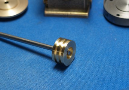
Boring bar arrived today so I got right to work with it.
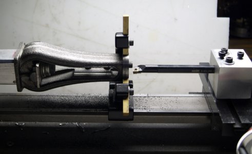
Not much material needed removing. I was pleased to find I managed to get the bore very close to the center of the frame, so all that work last week paid off. I'll need to clean up and drill the bosses for the slide valve bearings before I can take the frame off of the mandrel and finish the bottom end.
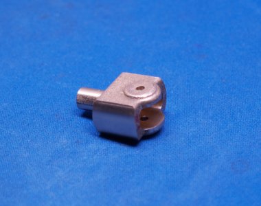
With that out of the way I started on the cross head.
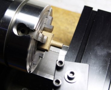
Turned this end down just enough to fit my 0.25" mill collet.
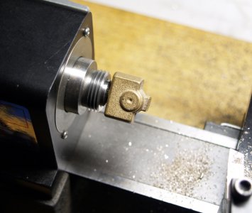
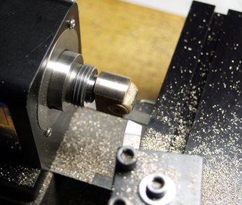
Finished diameter 0.749".
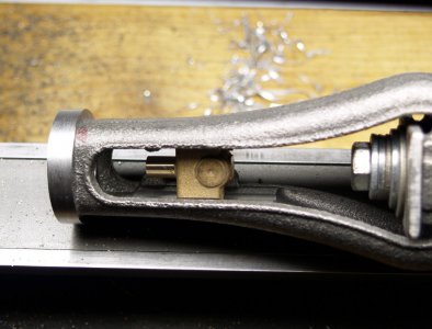
Nice fit.
Eric

Not much material needed removing. I was pleased to find I managed to get the bore very close to the center of the frame, so all that work last week paid off. I'll need to clean up and drill the bosses for the slide valve bearings before I can take the frame off of the mandrel and finish the bottom end.
With that out of the way I started on the cross head.

Turned this end down just enough to fit my 0.25" mill collet.


Finished diameter 0.749".

Nice fit.
Eric
Last edited:
- Joined
- Feb 15, 2020
- Messages
- 399
- Joined
- Aug 3, 2017
- Messages
- 2,437
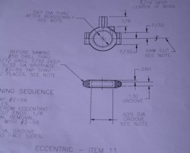
One of my future tasks I've been thinking about for a while now is this one. The eccentric requires an internal groove. Any suggestion on how best to do that?
View attachment 328540
Eric
Depending on how you do your setup, that should be pretty easily done with an internal-boring-bar tool on the lathe. You likely want to do it in the same setup as when you make the hole anyway.
Depending on your boring bar setup, you would just grind a bit with a square bottom and relief.
Are you a fan of Keith Appleton? In his videos he shows how to do all of the above operations. His humor can be a little dry, but he has really good solutions for a home hobbyist. I have just started collecting the stuff to do some steam engines this fall. Most likely the Stuart 10V and the Blackgates twin V.
Keep posting on what you are doing.
Keep posting on what you are doing.
- Joined
- Feb 15, 2020
- Messages
- 399
Are you a fan of Keith Appleton? In his videos he shows how to do all of the above operations. His humor can be a little dry, but he has really good solutions for a home hobbyist. I have just started collecting the stuff to do some steam engines this fall. Most likely the Stuart 10V and the Blackgates twin V.
Keep posting on what you are doing.
Yes, I've watched a lot of Keith's videos! Makes me want to take up another hobby!
Eric
- Joined
- Feb 15, 2020
- Messages
- 399
Milling the bosses for the slide valve bearings.
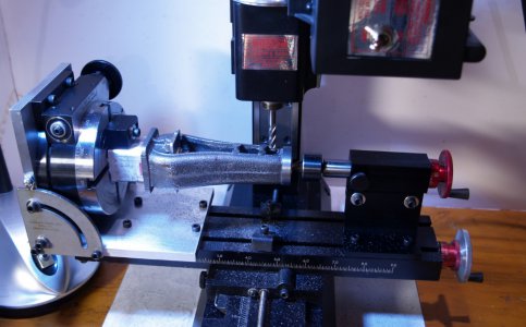
I had to get creative with measurements to figure out how much material to remove. I'll recheck it again but I'm pretty sure I'm within -0.004 of the mark. Close enough for me. Just need to drill and tap after I finish the slide valve bearings. That's three more tools to buy.
Not much space left on the mill table.
Eric

