The Journey Begins, PM Research #5.

I could be wrong, but if you remove a part from its holding device and re-position it isn't that a new setup? My understanding is that if you swap a part in a mill vice you introduce a new error. I wanted to avoid that.

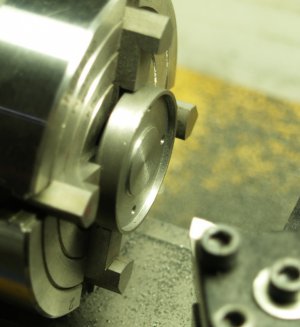
I chose to use a mandrel because no matter how many times I reverse it in the lathe (five times for this part) it's always on center with the previous cut and true to the lathe centers without having to indicate it in.

I look at each operation as a puzzle to be solved. I try to figure out the best method to get the results I need with the tools I have. If it takes 15 setups per part than so be it. BTW, I'm using manual Sherline tools without DRO.

Yes, but... The 'flipping' a part in the vice and indexing off a known flat surface is about as repeatable process that you can do. That said, I only did 2 setups for faces + bore + bolt circle. 1 for each side (excluding a 'skim' cut on each side to get a reasonably flat/measurable surface).

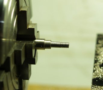
ETA: The problem I have with a mandrel/attachment to a shaft is how easy it is to spin the part and ruin it that way. I did it with my flywheel (OD was too small to get inside my vice jaws) where I put it on a shaft and set-screwed it on, then held the shaft. I hit a hard spot in the casting (or something) and spun the flywheel on the shaft. As a result my shaft has a nice 'thread' cut in it from the set screw.

I used an expanding mandrel on a different project (+ blue loctite and a set screw) and roasted my inner bore when it spun.

Additionally, using a critical dimension as a 'friction surface' just seems scary to me, it seems pretty easy to wear it out of shape/size.
 
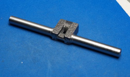
Started on the crank shaft today. The rough casting is slightly smaller than the plan dimensions in several places. The finish wasn't looking very good so I left it a couple thou over-sized. I can polish it once I get the rod journal finished.

crank1.jpg

Eric
 
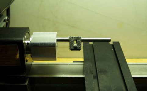
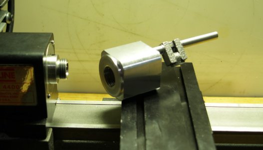
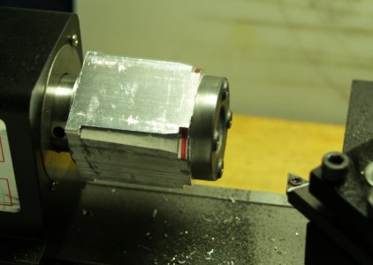
I was trying to figure out how to machine the rod journal and this is what I've come up with so far.
crank2.jpg
crank3.jpg

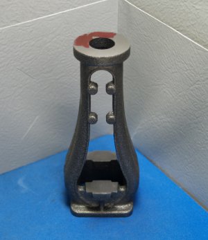
A lot of work has gone into that block of aluminum.

Eric
 
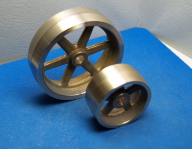
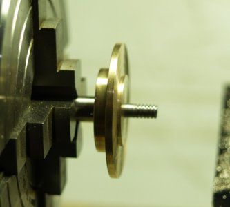
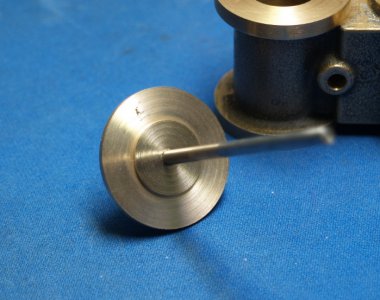
Found some time so I had a go at the flywheel and belt pulley today. I left the outer rims on both a bit thicker than the plans called for but I like the look.
wheels1.jpg
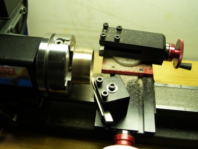
Both the flywheel and belt pulley have 5 degree crowns. Using the compound slide I cut one side well past the center, reversed the part and indicated in off of that fresh surface, and cut the other side to the center. I'm really happy with how these came out!

wheels2.jpg
I still need to drill and tap the set screw holes.

Eric
 
Started working on the frame today. Just trying to true the top and bottom for now. Clamped it standing up in the vise and used a fly cutter. There's only 5 1/2" space between the top on the vise and the end of the spindle on my Sherline 5400 mill, and this part is 4 7/8" tall. Barely enough space for the fly cutter to get in there. I had to use 1/4" lathe bits for parallels.

I managed to get the top and bottom surfaces parallel with each other but not square to the center line of the part so I'll need to fix that. I have about 0.050" to work with which should be fine. The top needs to be dead on, the bottom not so much. I'll fix it on the lathe.
frame.jpg

My 5400 mill doesn't have enough Z travel to bore for the cross head so I'll be doing that on my lathe (somehow). Or I could spring for that extended column and lead screw upgrade. Decisions decisions. I figure when I get done with this $110 model I'll have an extra $500+ in new tools. I'm well on my way to that now.

Eric
 
Last edited:
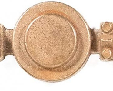
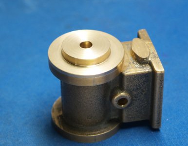
Worked on the bottom (inside) cylinder head today.
bhead.jpg

Turned the bottom in the 3 jaw chuck.
bhead1.jpg

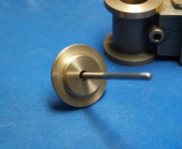
Made a mandrel to finish the outside diameter and mounting flange to thickness.
bhead4.jpg
bhead5.jpg

Then back in the 3 jaw to finish the center to thickness.
bhead2.jpg
bhead3.jpg

Starting to look like a something.

All of the bronze castings I've machined in this kit have had sand holes in them so far. I guess that's expected.

Eric
 
Last edited:
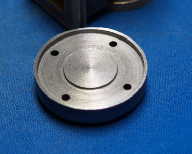
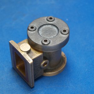
Here is the top head under construction. What I've done to it so far is faced the bottom surface, found the center of the bolt circle and drilled the holes. Then I made this wonky looking mandrel to turn the outer diameter using the bolt circle as a reference and drilled the bolt circle on it as well. To mount the head I put in some alignment pins and a drop of super glue. I removed the pins once the glue had set and went to work.
top head.jpg

Just like the crank shaft, this casting was undersized. I turned it down enough to give me an good outer edge to indicate off of when I put it back in the 4 jaw to finish the bottom. That left the OD about 0.005" under size and the blemish from where the runner was attached still shows. Oh well, I guess I can hide that with paint.

Eric
 
Back
Top