electronic lead screw

CL57Y sounds good but flaws may not show up for a while (if any). Will keep in mind, Thanks! Not sure what U mean by ''tweek the step rate in my code to mitigate..'' - normally the stepper is tuned in with the driver, which sometimes comes with a tuning software tool as per the CL57Y.
Does that mean, when U release the code, that users will have to tweek (if no software tool avail)? [technophobia is starting to show-eh!]
FYI, the pdf for their manual is a dud link: https://www.omc-stepperonline.com/download/CL57Y.pdf
Since the CL57Y has a USB rather than the "standard" RJ connector I'll be waiting for the manual to actually become available before I think about buying one. A USB connector ought to mean a USB interface, right?

I have a small lookup table that makes adjustments to the PWM period according to the number of steps output per spindle count. I was able to mitigate some small resonances that way and have less stepper whine. I actually started off dynamically varying the period according to RPM, but that introduces its own resonances. My results were pretty good with the simpler scheme so I went with that. I may be revisiting it. I've been pondering a "spread spectrum" scheme, but it already kind of does that just because of the nature of distributing the steps per spindle count for a given rate. We shall see.
 
Hi,

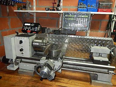
Here is my version of use of ELS on an Emco 8 lathe.

I can still use my lathe manually with a DRO
I can use my lathe as an CNC lathe with Mach3
I can use an advanced ELS with many features:
 Gearbox Left
 Gearbox Right
 Turning
 Boring
 Facing
 Parting
 Ext Thread
 Int Thread
 Ext Thread <0
 Ext Taper
 Int Taper
 Ext Radius )
 Ext Radius (
 Int Radius )
 Int Radius (
 Grinding
 Angle
 Settings

Have a nice day
 

Attachments

  • emco.JPG
    emco.JPG
    67.1 KB · Views: 384
Wow, Eurofox, sounds very slick, any details re controller?
Arduino based or commercial off the shelf?
 
I use the ELS system from Rocketronics and a genereric USB Mack3 4 axis + spindle with VFD interface.
You will find here on a French machinist forum more detail, you can use Google translator.
The ELS allow to "free" the steppers, this way is easy to use the lathe in the manual mode with a DRO.
 
I use the ELS system from Rocketronics and a genereric USB Mack3 4 axis + spindle with VFD interface.
You will find here on a French machinist forum more detail, you can use Google translator.
The ELS allow to "free" the steppers, this way is easy to use the lathe in the manual mode with a DRO.
Oh, thought it was your design, couldn't tell from photo. So I assume ELS4? (Big $$ landed here, Oz)
 
Designed and printed some parts to fit the encoder to the spindle:

IMG_0474.jpeg


Mounting consists of a bracket, spindle / shaft coupler and a stud that is threaded to screw into an existing mounting hole (it used to have a cap head that helps hold the side of the gear box case to the headstock)

IMG_0475.jpeg
IMG_0476.jpeg


Here's STLs & STEP files on thingiverse... it might be of help to other SC4 owners (usual caveats apply - just because they fit my lathe, doesn't mean to say it will fit all SC4s)

 
Last edited:
Designed and printed some parts to fit the encoder to the spindle:
(pics clipped)
Mounting consists of a bracket, spindle / shaft coupler and a stud that is threaded to screw into an existing mounting hole (it used to have a cap head that helps hold the side of the gear box case to the headstock)

Here's STLs & STEP files on thingiverse... it might be of help to other SC4 owners (usual caveats apply - just because they fit my lathe, doesn't mean to say it will fit all SC4s)

Very nice work bro., the Prusa i3 Mk3 any issues? jams? what material ? heard that there's a new printable material out that's 4 x tougher than ABS!
 
Very nice work bro., the Prusa i3 Mk3 any issues? jams? what material ? heard that there's a new printable material out that's 4 x tougher than ABS!

Its a good printer, with loads of support from an active community. I have had jams in the past, but not had any recently. Those parts are printed in PETG. It’s like a half way house between ABS and PLA. Easy to print, but stronger and UV stable.
 
I have collected all of the components for my ELS with the exception of the drive belt for the encoder and the machining is completed except for mounting the encoder bracket.

The NEMA 24 stepper fit nicely in the opening at the base of my G0602 lathe. A 130 to 136 tooth belt will work in this position. Rather than machine the flanges of the GT2 drive pulley as Clough42 did, I counterbored the pulley to accept the e clip.
ELS Mod 2 .JPG
.......
ELS Mod 3 .JPG

Time to start on the electronics. I resurrected my ESD mat and am ready to assemble and test the circuitry.

I have one question for the group. I have elected to go with a 1:1 drive for the stepper and will need to change the 3:1 ratio. I am having trouble locating where the stepper pulley ratio is defined in the source code. If anyone can direct me, I would appreciate it.
 
Watch Part 2 for how he works out the numbers. I'm facing the same issue, made more fun by the additional reduction inside my QCGB.
 
Back
Top