Ball Turner Experience

After speaking with Jim a bit, here's what his design looks like for his super-simple ball turner with fixed radii that you can make from scrap and attach to any compound:

View attachment 454681

(view from the back of the lathe)

The parts are a tee-nut base, a swivel puck, a handle, a cutter (worn out end mill or whatever), some set screws, a long screw (sized to fit the radii you need) and a couple nuts. The tee-nut should be slightly proud of the compound top.

Since most of us have our compounds semi-permanently mounted, this design conveniently fits in the tee slot of the compound. Four set screws secure it in the slot securely.

The swivel puck is just a piece of CRS of convenient size. Drill and (optionally) ream a hole that's a fairly precise fit for a socket-head cap screw through the swivel base and the end of the tee-nut, then capture the swivel base with a cap screw and two nuts (one to adjust the tightness and another as a lock nut).

Find an old worn out end mill or whatever to use as a cutter, and grind one end perfectly flat and perpendicular to the sides. You want a sharp edge all the way around the circular top of the cutter.

Drill and (optionally) ream a hole the same size as the cutter through the cylindrical swivel exactly the desired radius from the center of the cylinder minus the radius of the cutter you chose. I thought this had to be a blind hole to bear against the cutting forces. A flat bottomed hole exactly the right depth to position the cutter at center height would be a PITA to make, but Jim says a grub screw in the side is more than sufficient to bear the cutting forces and is a whole lot easier to adjust.

Finally, mill a flat at an angle and drill and tap a hole for a handle at a convenient location (or three).

Notes from our conversation:
  • This has a zero rake angle and no relief. This is not an issue in practice (witness Jim's video above). It's basically a tangential turning tool for already cylindrical stock, but it won't work for for facing. Since the cutter is at or slightly below center height, you don't need any relief (the work itself already falls away).
  • The zero rake angle is actually fine for even harder materials, but the lack of any chip breaker can make for some scary chips. But only the final pass will stay in contact with the entire sphere (and since you're swinging the handle manually I imagine it's easy to break chips like pecking while drilling).
  • Note that the swivel puck diameter and thickness affects the maximum diameter ball that can be turned. When you feed in enough on the cross slide to make the final pass at the final sphere radius, the puck must not interfere with the bottom of the work.
  • In use, the cutter is behind the axis of rotation, of course, but you want the handle attached to the right so that you can cut almost a complete sphere (or as narrow a shaft as you like for ball handles).
  • Of course, there is nothing preventing you from drilling holes at multiple different radii!
  • Jim is the master of keeping things simple. He points out that we usually don't need a tool with a continuously adjustable radius. We just need a tool that can cut the radius we need RIGHT NOW. In practice, how many different sizes do we really need? If you don't have a puck with the radius you need, just drill another hole in one at the correct offset and drill and tap another hole in the side for another grub screw. In my case, I'm mostly putting a relatively small ornamental ball at the end of a lever, so the size isn't particularly critical anyway. I've no need for turning 6" spheres.
I'll be making one of these over the coming days, and probably remaking some of the umpteen ball handles on my Quorn (just two radii required). I'll post an update if I learn anything new.

I'll also be posting another thread on how Jim makes and polishes/laps his radius form tools. As usual, super simple and effective.
Rex
Your picture shows the radius tool extending from the radius axis not the radius swing distance from the radius axis. And if you could make the tee nut base part a different color it would make it easier to visualize. I will see if I can send you a picture of this latter today.
jimsehr
 
Your picture shows the radius tool extending from the radius axis not the radius swing distance from the radius axis.
I don't follow. Do you mean the pivot for the radius (the purple SHCS below) doesn't need to be in the very center of the puck (blue), it can be off center? Or do you mean the entire compound can be retracted if you just wanted, say, to just fillet the edge at the face of the work?

Screenshot 2023-07-23 at 9.19.53 AM.png
As I understand it, if the pivot point (purple SHCS) is under the center of the work, it will turn a sphere. In use, you would start with the pivot toward the operator (cross-slide retracted) then gradually feed in the cross slide taking cuts until the pivot is under the center of the ball for the final pass. Of course, the cutter (yellow) must be behind the pivot point to turn a convex surface.

The distance from the inboard edge of the cutter (yellow) to the center of the pivot (purple screw currently in the center) determines the radius of the sphere, no?

The parts are rotated weirdly in the image above, but that's just because I haven't bothered to model the motion yet.
 
I don't follow. Do you mean the pivot for the radius (the purple SHCS below) doesn't need to be in the very center of the puck (blue), it can be off center? Or do you mean the entire compound can be retracted if you just wanted, say, to just fillet the edge at the face of the work?

View attachment 454728
As I understand it, if the pivot point (purple SHCS) is under the center of the work, it will turn a sphere. In use, you would start with the pivot toward the operator (cross-slide retracted) then gradually feed in the cross slide taking cuts until the pivot is under the center of the ball for the final pass. Of course, the cutter (yellow) must be behind the pivot point to turn a convex surface.

The distance from the inboard edge of the cutter (yellow) to the center of the pivot (purple screw currently in the center) determines the radius of the sphere, no?

The parts are rotated weirdly in the image above, but that's just because I haven't bothered to model the motion yet.
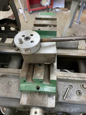
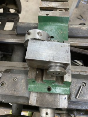
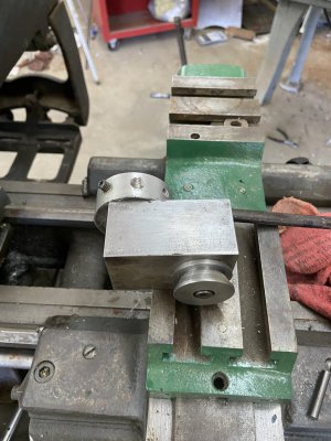
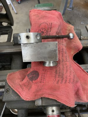
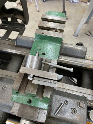
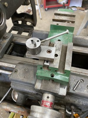
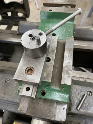
I took a couple pics of two turners I made.
The colors make it much easier to visualize. But the tool kind of makes it look like it is on axis. So I am sending you a few pic of 2 turners showing how they fit different machines.
 

Attachments

  • 055496FB-BEF1-4E6D-9504-89C1B743783D.jpeg
    055496FB-BEF1-4E6D-9504-89C1B743783D.jpeg
    287.9 KB · Views: 20
  • 60AFF812-C3C7-410A-82B6-4718481F2D6E.jpeg
    60AFF812-C3C7-410A-82B6-4718481F2D6E.jpeg
    263.9 KB · Views: 20
  • 8B6491DA-98C9-43E5-9696-32F4E4946C4B.jpeg
    8B6491DA-98C9-43E5-9696-32F4E4946C4B.jpeg
    293.4 KB · Views: 17
  • 758BA4C8-9C88-42CA-BF69-01118781EEDA.jpeg
    758BA4C8-9C88-42CA-BF69-01118781EEDA.jpeg
    323.4 KB · Views: 17
  • 885C33DC-26DE-41CE-93AF-18183A33ABB8.jpeg
    885C33DC-26DE-41CE-93AF-18183A33ABB8.jpeg
    325.2 KB · Views: 18
  • 37B9850B-FFD0-465C-9FE6-7AD309DEE190.jpeg
    37B9850B-FFD0-465C-9FE6-7AD309DEE190.jpeg
    319.9 KB · Views: 16
  • 87514BDB-AA7C-469D-B3A6-B90FF68BDC1B.jpeg
    87514BDB-AA7C-469D-B3A6-B90FF68BDC1B.jpeg
    302.8 KB · Views: 22
But the tool kind of makes it look like it is on axis.
I think the photos and model should clear up any confusion, but I spoke with Jim and he wanted to make two things clearer:

The cutter rotates around the pivot point, it's not the center of rotation (it wasn't as obvious in the uncolored image). The pivot point is the central SHCS. Here's a plan view that shows it approaching the work to turn a ball on the end of a shaft:

Screenshot 2023-07-23 at 10.12.52 AM.png
He also wanted to emphasize the importance of ensuring the tee nut (green) is proud of the top of the compound (purple). Otherwise the swivel puck will bind up on the compound.

I modeled a 3/8" turning radius (for a 3/4" diameter ball end). For different radii, you would just change the distance from the center of the pivot to the edge of the cutter.

To use:
  1. Put a piece of stock in a collet or chuck that's at least 3/4" diameter (minimizing stick-out of course -- I didn't need to draw the work so long). Retract the cross-slide.
  2. Turn down a section with the desired "neck" diameter, and create a 3/4" diameter cylinder at the end exactly 3/4" long.
  3. Move the carriage until the center of the pivot point is 3/8" from the end of the stock, in the middle of the cylinder at the end.
  4. Start nibbling away the "corners" of the cylinder on the end, gradually feeding in the compound for each pass.
  5. Stop when the pivot is directly under the spindle axis. At that point you are turning a true sphere.
---

Sorry to hijack the thread, but it seems to make sense to continue the conversation here rather than moving it.

My little Quorn grinder has three sizes of ball ends on the bazillion little lever arms: 3/8" radius, 1/4" radius, and 3/16" radius.

I successfully made all of the ball ends on my little 10" lathe using a form tool upside down on a rear-mount tool post, but forming the largest 3/4" diameter balls was a bit challenging. I wouldn't have wanted to try it in anything harder than leaded steel. I do want to remake a few of them that came out poorly (for various reasons).

The two smaller radii were easily done with form tools, though, and it probably would have been fine holding the tools on my QCTP. I'm not sure it's worth worrying about turning vs. forming such small balls, but them's the sizes I needs.

As I started to think about making one of Jim's ball turners to make some more Quorn handles, I realized that the smaller radii are problematic with this design. The smallest diameter cutter I want to attempt is a 1/8" carbide shank from a broken 1/16" endmill. For the smallest ball, that means I'd need the center of the hole for the cutter to be just 0.125" from the center of the puck. The edge of the cutter will be just 1/16" away from the center of the puck, right where the head of the cap screw is.

I could get around the problem by not using a cap screw inserted from the top. I could thread something in from the bottom to use as the pivot. Then I can bore the cutter holes wherever I want (as long as I bore blind rather than through holes).

Further, the cutter would be so far from the edge of the puck, that I'd need a deep hole for the set screw. Rather than using a tiny set screw in a deep hole, I'd probably use a shorter 1/4-20 set screw with a shaft inserted in a smaller diameter cross hole to bear against the cutter. This is the kind of feeping creature that Jim hates.

Alternately, I could just continue to use form tools for the smaller balls and make a dedicated 3/4" diameter (and larger) ball turner.

I keep going back and forth on which option I prefer, but it would be neat to make one ball turning tool that can form all three ball sizes.
 
Last edited:
I think the photos and model should clear up any confusion, but I spoke with Jim and he wanted to make two things clearer:

The cutter rotates around the pivot point, it's not the center of rotation (it wasn't as obvious in the uncolored image). The pivot point is the central SHCS. Here's a plan view that shows it approaching the work to turn a ball on the end of a shaft:

View attachment 454752
He also wanted to emphasize the importance of ensuring the tee nut (green) is proud of the top of the compound (purple). Otherwise the swivel puck will bind up on the compound.

I modeled a 3/8" turning radius (for a 3/4" diameter ball end). For different radii, you would just change the distance from the center of the pivot to the edge of the cutter.

To use:
  1. Put a piece of stock in a collet or chuck that's at least 3/4" diameter (minimizing stick-out of course -- I didn't need to draw the work so long). Retract the cross-slide.
  2. Turn down a section with the desired "neck" diameter, and create a 3/4" diameter cylinder at the end exactly 3/4" long.
  3. Move the carriage until the center of the pivot point is 3/8" from the end of the stock, in the middle of the cylinder at the end.
  4. Start nibbling away the "corners" of the cylinder on the end, gradually feeding in the compound for each pass.
  5. Stop when the pivot is directly under the spindle axis. At that point you are turning a true sphere.
Also if you are swinging a 1 inch radius you can stop the spindle and mic the dia . If it reads 1.005 you know you have .005 more to go on the dial.
jimsehr
 
Also the farther tool cutting edge is below true center your radius size changes.
 
Jim: would you bother cutting really small ball ends (1/2" diameter and smaller) or would you just use a form tool?

For anyone else interested:

Jim's trick for grinding form tools to a precise radius is to mark the desired radius with gauges onto a HSS blank, then grind it out as close as you're able to get to the line on a pedestal grinder by hand (with a bit of relief angle). You then lap in the final shape on the lathe:
  1. Cover up the ways to protect from any grinding/lapping grit.
  2. Insert a piece of scrap into a collet (safer than spinning chuck jaws) with a larger diameter than the desired radius. 1018 or 12L14 leadloy is fine. Pretty much anything will be softer than the HSS.
  3. Turn down a stub on the end of the desired diameter.
  4. Coat the stub in abrasive. Jim uses a slurry of carbide grit collected from the green wheel on his grinder and way oil, but diamond paste, valve compound, carborundum, whatever works.
  5. Hold the rough ground HSS tool blank by hand, and present it to the side of the stub with the lathe turning at a reasonably slow speed (you don't need back gears, but you don't want to sling grit everywhere either). Angle it slightly less than the relief you ground, and work it back and forth along the side of the stub until the tool has a polished edge precisely conforming to the curve on the periphery of the stub lap.
  6. Turn down the diameter of the stub a bit before cleaning up (to get rid of the embedded grit) if you plan to use the stock as anything but a lap again.
 
Amazing.

You’re gonna get me to attempt some of these eventually. I like the double rings on the ball handle best.

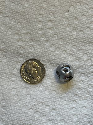
I know you did a turners cube with a ridiculous number of captive cubes. Was it four cubes total?
 
Back
Top