Wells-Index 847 Milling Machine - Ownership Thread

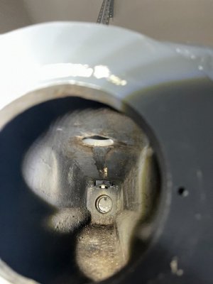
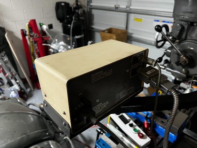
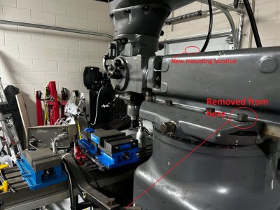
Aso removed the arm that holds the DRO display. I did not like how it was mounted. Previous owner attached it to one of the bolts that hold down the gib.

I need to buy a washer as the one there is gone.
IMG_5010.jpeg

My plan is to flip the arm around and install it from the top. There is hole there, big hole that will require some large washers. Either that or drill and tap a hole to secure it.

Doing all this for two reasons. (1) I really do not think that the arm should have been secured from that bolt and (2) I need it to be more sturdy so that I can install the VFD control box on the bottom of the DRO Display. So everything is within reach, but also able to swing away if needed.
 
Last edited:
Make one! I know you have a couple of lathes... Quick and easy job!
I need to start defaulting to thinking like that instead of "I need to buy".... have to do a mindset shift to "I have to make that"...
 
I need to start defaulting to thinking like that instead of "I need to buy".... have to do a mindset shift to "I have to make that"...
It takes a little while to get there, but is definitely rewarding. I'm sure you have plenty of scrap you can make stuff from by now. Think about it, you have thousands of dollars of machinery, knocking off a washer is like what, less than a minute or two?

Instead of being helpless with a broken gear shaft on my lathe, I just made another one on my mini-lathe. It only took a day, and that's because I messed around with an alternative design. Once I gave up on my "great idea" and decided to copy the existing, it didn't take long at all. I bought spare parts from Grizzly, but haven't installed them, as my copy of the gear shaft is still in service.
 
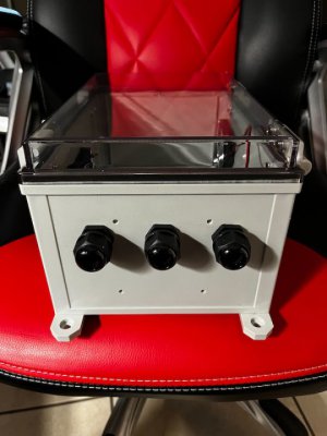
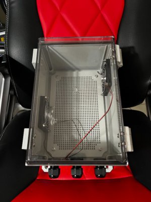
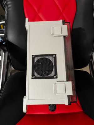
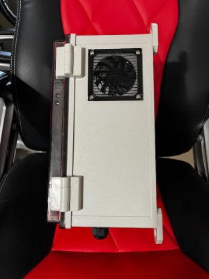
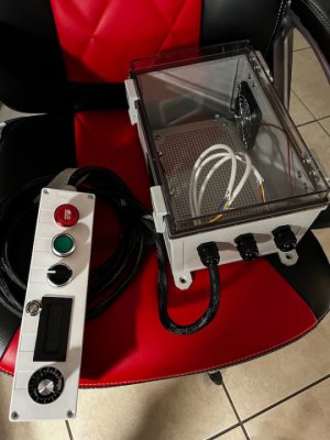
Okay... enclosure arrived. Drilled the holes for the fans and cable connectors...

Yeah... I forgot that the cables were coming from the bottom... I had drilled holes for a fan in there, lol.

IMG_5048.jpeg
IMG_5054.jpeg

Only missing the plastic cover over the filters. Those arrive tomorrow.

IMG_5055.jpeg

Only missing the plastic cover over the filters. Those arrive tomorrow.

IMG_5056.jpeg

Done.

IMG_5061.jpeg

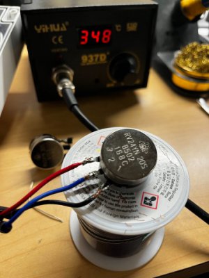
Also replaced the 10K ohm potentiometer with the correct 5K ohm.

IMG_5059.jpeg

So finally ready to be installed.
 
Last edited:
So remind me, what did you ultimately decide for controlling the power to the VFD. Are you going to use the breaker you had mentioned earlier
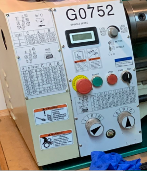
For mine, I would love to implement the behavior of my grizzly lathe. It has a VFD embedded in the back of the lathe. It uses 1 NO and 1 NC momentary buttons connected to a magnetic contactor to engergize the entire lathe or to turn it all off. The motor doesn't start until I turn the 3 position switch to fwd or rev. It would be pretty cool to have a pendant for the mill that could do the equivalent. ...Control the master power to the VFD which in turn would power everything.

1648593276935.png
 
So remind me, what did you ultimately decide for controlling the power to the VFD. Are you going to use the breaker you had mentioned earlier
For mine, I would love to implement the behavior of my grizzly lathe. It has a VFD embedded in the back of the lathe. It uses 1 NO and 1 NC momentary buttons connected to a magnetic contactor to engergize the entire lathe or to turn it all off. The motor doesn't start until I turn the 3 position switch to fwd or rev. It would be pretty cool to have a pendant for the mill that could do the equivalent. ...Control the master power to the VFD which in turn would power everything.

View attachment 402278

Plug from the wall to a small breaker box -> to VFD. Correct. That is just to kill all electricity to the machine. Right now I am just plugging and unplugging from the wall during the testing. Need to get the breaker box with the correct breakers amperage.

I just kept it simple... wiring as you suggest would be nicer than what I did for the overall power switch. Everything else works as you describe, mill does not run until I flip the FWD/STOP/REV switch.
 
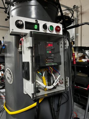
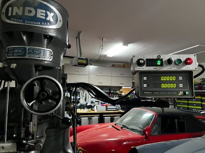
Okay... almost done with the wired-remote. Only need to install the RPM/Tachometer... need a mount for the pickup sensor and to make the wire harness longer.

IMG_5083.jpeg

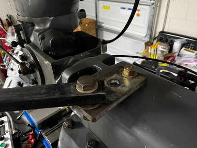
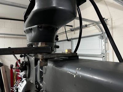
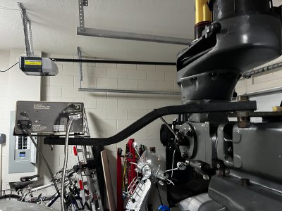
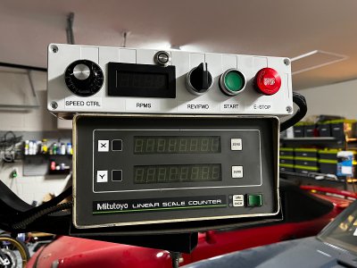
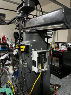
Moved the arm from the bolt that tightens the gib to the top... there was a hole there. Used some Delrin blocks drilled with a hole to accommodate a bolt... worked like a charm.

IMG_5084.jpeg
IMG_5089.jpeg
IMG_5085.jpeg

IMG_5086.jpeg

Cleaned the DRO display housing, removed the marker X and Y that were there... replaced with some printed labels. Double face tape to secure the wired-remote control box (later I will make a bracket for it)

IMG_5088.jpeg
IMG_5092.jpeg

IMG_5097.jpeg

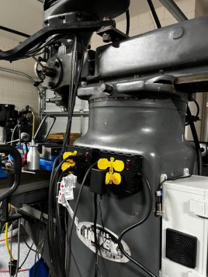
Two 4-receptacles extentions

IMG_5094.jpeg

IMG_5095.jpeg

And a quick video...

 
Last edited:
Back
Top