- Joined
- Sep 28, 2013
- Messages
- 4,306
a very VERY big thanks to George Bulliss for his help with this - it would have been considerably harder without the help file and sketch.
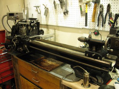
Got the treadmill motor running with an MC2100 drive and Arduino a few moments ago, super pumped about that. This is the motor that was on my Atlas 618 and it will be going on my new to me South Bend wide 9. I know that the MC60 drive that's on my lathe and mill can't give this motor the beans it needs, which isn't a big deal on the Atlas (can't use those beans) but probably will be on the SB. The MC60 is a piece of cake to wire up and just needs some switches and a speed pot. The MC2100 is much more powerful but needs a digital PWM (pulse width modulation) signal to change speed. You can (maybe) use a doodad off Amazon, you can also buy a very reasonably priced PIC based board of our own Maxheadroom or you can use an Arduino to generate the signal based on an analog pot input.
I chose the latter because I'm cheap, stubborn and wanted to learn something new. All of which played out in this The sketch (code or program in Arduino speak) is based off of the one here https://sonsofinvention.wordpress.c...100-controller-and-lathe-tachometer/#more-389, but is a more stripped down version that George made or found.
Spent a bunch of time banging my head and grinding my teeth until I figured out what to do to compile the sketch, then it didn't work. Spent some more time banging my head and grinding my teeth until I realised the sketch and the wiring diagram differed in the switch pin. Changed that and it all worked! I set the max PWM at 950/1023 (94% of max motor speed) because over that the drive would shut down.
SUPER HAPPY!
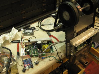
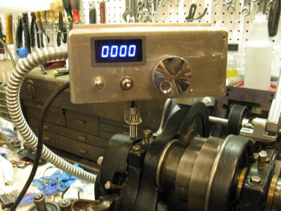
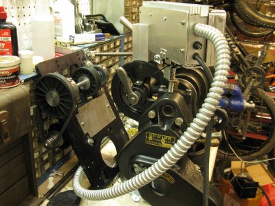
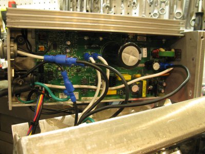
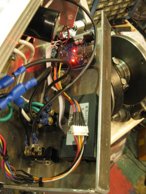
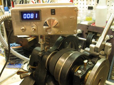
looks like a mess because it is Next I need to see if I can power the tach off of the MC2100 board (which is powering the Arduino) and once that is done start packaging it into the drive box to go above the headstock. I realised it can't go on the motor plate as I need a reverse switch on the motor leads, so it has to all go in one box rather than a control box on the headstock and a drive box on the motor plate. WOOHOO!
Got the treadmill motor running with an MC2100 drive and Arduino a few moments ago, super pumped about that. This is the motor that was on my Atlas 618 and it will be going on my new to me South Bend wide 9. I know that the MC60 drive that's on my lathe and mill can't give this motor the beans it needs, which isn't a big deal on the Atlas (can't use those beans) but probably will be on the SB. The MC60 is a piece of cake to wire up and just needs some switches and a speed pot. The MC2100 is much more powerful but needs a digital PWM (pulse width modulation) signal to change speed. You can (maybe) use a doodad off Amazon, you can also buy a very reasonably priced PIC based board of our own Maxheadroom or you can use an Arduino to generate the signal based on an analog pot input.
I chose the latter because I'm cheap, stubborn and wanted to learn something new. All of which played out in this
Spent a bunch of time banging my head and grinding my teeth until I figured out what to do to compile the sketch, then it didn't work. Spent some more time banging my head and grinding my teeth until I realised the sketch and the wiring diagram differed in the switch pin. Changed that and it all worked! I set the max PWM at 950/1023 (94% of max motor speed) because over that the drive would shut down.
SUPER HAPPY!

looks like a mess because it is


