Mike's SCARA Robot

I can understand the primary purpose of just learning how it works and can I fix it, followed by programing it for what ever. That would have been enough. I could see this as a tool changer but would be concerned with chips or coolant getting at the electronics. Maybe it is waterproof but didn't look like it.

I love the mechanics of the arm. Beyond what you have already done, which as I said would be a satisfying project alone, it really doesn't matter what you do with it. That is along as you are enjoying yourself.

I have designed and built machines many times over the years. Could have gone and bought one but always like the challenges and felt I could do it better. For me, it has to look like it came out of a factory and performs. Once I get past that, it is more of what is next.

But now that I think about it. That could be a great way to feed cases into my annealer that I built or some other reloading process. Maybe take the measured powder from my Sartorius lab scale that I use for my competition loads and drop it into the case for me. Not necessary but would be cool.

As far as chips and coolant, I can have the arm move to a parking location behind a closing door. The robot itself is not waterproof in any way.

I'll post projects as I think of them for the robot. I'd love to also get a 6 axis robot arm at some point like a Fanuc 200iC/D. We will see, they are very expensive - even in the used market.
 
Last edited:
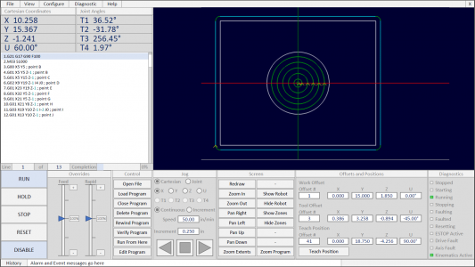
Drew up a quick PowerPoint sketch of how I want the HMI to look:

1602619777671.png

From the top,

Menu Bar
A Windows-like menu bar allows for basic program control, navigation to pop-up screens, and system settings. I'd like everything to be able to be configured from here rather than needing the PLC software. The X in the top right corner closes the application.

Coordinate View
Shows robot cartesian coordinates as well as the joint/motor angles.

Toolpath Display
A live data display will show toolpath lines as they are executed as well as the current tool position. The HMI software is going to be lacking some features in this area that I'd like, but I'll do the best I can

Code Window
A scrolling code window will highlight the current line of code. The current line of code is displayed and may be changed when the program is not running. A completion bar will show program completion in percentage of total lines of code. The program will be able to execute G-code (limited feature set at first) and robot code (I haven't decided on which language to use - or to create my own).

Command Buttons
Large buttons on the left control the startup and operation of the robot. The robot will automatically home when enabled. Run will start the program, hold will pause motion and allow the program to be resumed, stop will end the program, and reset will reset faults if needed. Buttons will be disabled when not able to be used.

Override Pane
Two sliders control the speed and rapid overrides

Control Pane
The control pane allows the user to load and manage programs. Programs are stored in PLC string memory arrays. If the program is too long (~>70000 lines) the program will be broken into multiple different arrays. The programs should be loaded from flashdrive containing text files. VBA scripting will transfer the file contents line by line into the PLC memory. This is tricky but I've done it before. A code editing window will be made available which can edit the code in PLC memory, not on the flashdrive. Run from here can be selected to start the program midway through while executing modal changes preceding the current line. Verify program will check program execution for errors and out of range motion, without moving the motors.

Jog Pane
The jog pane allows the user to jog the robot, either in cartesian coordinates or joint angles. The jog can be continuous or incremental. Jog speed and jog increment are programmable and will be retained for each axis when deselected. Forward, reverse, and stop buttons (for incremental movement) are available

Screen Pane
The screen pane gives the user controls to change the toolpath display (which is unfortunately not click interactive). I want to add a robot overlay to the screen, mimicking the mechanical shape of the robot. I also want to consider adding reduced speed and avoidance zones to help the robot not crash with hazards inside the workspace.

Offsets and Positions Pane
This pane will allow the user to edit the work and tool offsets. These selections are read only when the program is running and will update to show the current work and tool offset selected. The teach position zone will allow the user to edit saved positions and teach new ones. These positions may be referenced in the code execution by calling a P# variable.

Diagnostics Pane
Finally, the diagnostics pane indicates the current mode of the robot state machine and indicates other important diagnostics.

Bottom bar
The bottom bar shows the current diagnostics message plus offers a button to open a message history popup. There is blank space here to add additional features


Still thinking up features! I can add tabs and sub menus on the screen as needed, but right now I don't think any are needed.
 
Thought of a few items I do not have in the display above. I'll need to find a way to elegantly add them.
  • Multiline Manual Data Input (MDI)
  • Single Block Execute Select Button
  • Block Skip Select Button
  • Optional Stop Select Button
  • I/O control pop-up window
  • Motor Tuning pop-up window
  • Soft limits configuration pop-up window
  • Workspace bubble configuration pop-up window
  • Avoidance Zone configuration pop-up window
  • End of Arm Tooling (EoAT) control window
I got a good start on the HMI development yesterday. I'll post some updates. I also plan on posting a little overview of the PLC programming software and HMI development environment if anyone is interested.
 
OK, PLC Software.

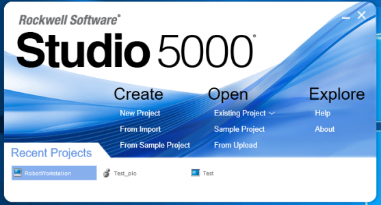
I'm using Rockwell Automation's Studio 5000 PLC development software (Version 33).
1602864041156.png

PLC's differ from your standard microcontroller in a number of important ways. First off, they are designed for large amounts of I/O which someone else has done the leg work of developing the interface for you. There are dozens of flavors of I/O modules and all of them are designed to plug into the PLC rack and have a data assembly automatically created for you as soon as you add them to the program. Next, PLC's are designed for networking and connectivity. All of the network processing is handled in the background and typically does not affect the execution of you runtime program. PLC code is interpreted (meaning no compiling) so you are able to "go online" with the PLC and watch it execute your code. Online edits to the code while the PLC is running are perfectly fine in most cases. Rockwell PLCs have 4 languages (Ladder logic, structured text, function block, and sequential function chart) which can be used interchangeably. Ladder logic is the easiest to read, especially at runtime.
1602866549636.png

PLCs are also excellent for real time program control and time dependent control (think of timers and scheduled code execution). This is perfect for machines since they have real world characteristics which require time delay in your code.

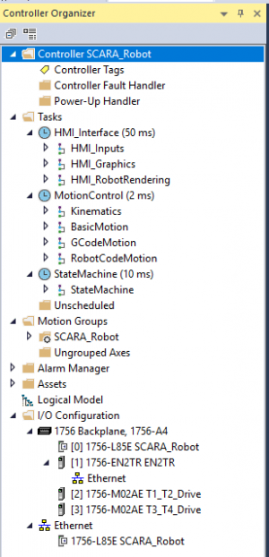
Here is the controller organizer for the PLC. From top to bottom... The Controller tags contains all globally scoped tags (PLC name for variables) in tabular format. Your actual code is organized into tasks. Tasks can occur on a schedule (periodic tasks), driven by an event (event tasks), or run continuously with whatever remaining processor power is left (continuous task). Each PLC can handle up to 32 tasks, although you typically only have a few. Inside each task are programs, you can have 1000 of these per task. Finally inside each program are routines (no limit on this). Programs may have their own locally scoped tags which can only be used by that program. Here I am using 3 periodic tasks (2ms, 10ms, and 50ms).

The motion group contains all the motion axes and coordinate systems for this PLC. I have 8 axes (T1, T2, T3, T4, X, Y, Z, and U) and 2 coordinate systems (cartesian and robot). The motion group can update every 2ms.

Finally at the bottom is the I/O tree where all the connected devices are stored. I have the PLC, an Ethernet interface module, and (2) 1756-M02AE analog motion modules.
1602866039152.png

Here is an example of some simple ladder code. Ladder logic was created to be easily read by electricians familiar with relay logic. In the rung below, the logic statement is: IF (A and NOT B OR C) THEN X = 1. There is also the parallel statement: IF ((A and NOT B OR C) AND D) THEN Y = 1.

1602867260184.png

Here is an example with a timer which would be a touch tricky to do in an Arduino without stopping the processor. The statement is: IF A THEN start TIMER. IF A AND TIMER DONE THEN X = 1. The timer is preset to 1000ms and the accumulator will count up on screen until 1000 is reached. DN is a status bit indicating the timer is done

1602867568280.png

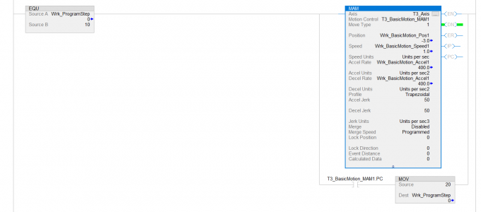
Here is an example of the real code running the robot. When the program counter tag (Wrk_ProgramStep) is equal to step 10, then execute the MAM (Motion Axis Move) instruction. This commands the axis T3 (Z axis motion) to move incrementally the distance contained in the tag (Wrk_BasicMotion_Pos1) which is currently -3 inches. The move should use the speed and accelerations contained in the tags shown below (current values are displayed with the tag), and the motion should follow a trapezoidal profile. The rest of the arguments in the instruction are advanced features not used at this time. The tag T3_BasicMotion_MAM1 is a unique tag containing the information pertinent to this motion instruction.

After the instruction is executed, the PLC sits on this rung of code until the status bit T3_BasicMotion_MAM1.PC (Process Complete) is set, then the program jumps to step 20. Motion programming is one of the most intensive tasks for a PLC. The PC bit is set when the PLC is done commanding motion and the command for the axis to reach its final destination has been sent.
1602867769346.png

I can't cover every detail of the program, but this is a quick and dirty introduction. Feel free to ask any questions.
 
I'm having an interesting thought session on the PLC program memory.

My PLC can store up to 40MB of tag (variable) memory, which includes all the data needed to make the program work in addition to saved robot/Gcode programs. Programs will be stored in arrays of strings where each array must not exceed 1.5MB - I'm calling this a Block. If a program is longer than one Block, then it can use a second, and my code will pickup on the second block where the first left off.

Here's the tricky part. The default String datatype in the PLC holds 82 characters and the largest array <1.5MB is 17873 indices. This is essentially the number of lines in the program. If any line (e.g. "M03 S1000") is shorter than 82 characters, then the extra characters are used to hold a null character and are useless.

I can opt to define a String datatype shorter than 82 characters (let's use 41) and now the largest array is 35746 indices. I trade number of characters per line for more lines of program code. The problem comes however, if I ever have a line that is longer than 41 characters, then the data is truncated when it is loaded into the PLC. I could probably flag this error during the data transfer, but I can't fix it.

My CAM software often creates very long programs (hundreds of thousands of lines) with tons of small moves. I want to be able to use these. The trick will be trying to come up with the optimal number of characters per line so I don't truncate data in 99.9% of cases, but I don't waste any more data than is needed.

BTW, if I assume a 41 character length of string, then I can store a total of 714,920 lines of code distributed between 20 (or more) Blocks. This reserves 25% of the controller memory for use by the program. Once these Blocks are full, I will have to delete programs from controller memory before loading new ones. I'll also need to create some sort of file system manager that tracks which blocks belong to which program, and what memory is available for use/free to load data into.

OK, to start out, I made a memory block datatype with a length of 55 characters. This is because it is longer than the longest gcode string I could quickly think of (I'm not planning on adding canned cycles or anything crazy here...) which was "N12345 X12.3456 Y12.3456 Z12.3456 U12.3456 F123.45". Also my current HMI screen can only display 55 characters...

Each data Block is 25000 lines long and equals exactly 1.5MB of controller memory. I made 10 blocks to start out, consuming 15/40MB available on the PLC.

1602955509838.png

This can easily be changed in the future if it is a problem.

The way I'm planning on making this work is this. There will be a file manager object in the PLC code. Its job is to track which programs are loaded and what memory blocks (in which order) are used to save that program. It needs to help the Gcode interpreter know which line of which block it should read from when the robot is running. It also marks which programs are empty and will interface with the HMI VBA code to load programs from flash drive into PLC memory.

All this data is contained in a "Program Ledger" which has the program name, a bit to identify if it is empty, a bit to identify what language the code is in, and an array of integers to identify which memory blocks the program is stored in and which order they should be loaded in.

I'm not quite sure if I am going to have the Gcode interpreter read directly from the memory block, or if the memory block should be copied to a working tag before being read.

Honestly, I'm making this a lot more complicated than it needs to be. I could simplify this by only allowing a single 25000 line program in the PLC and reading directly from that. I think the file system would be kind of neat though!
 
Last edited:
After reading through this thread I thought I was at work back in the mid 90's. Glad all I had to do was design the mechanics and electrical interfaces.
Some "hobbies" people have around this site.
Add a linear track to that and you could have it serve drinks to people of all sizes down a bar.
 
is it hard to change the max number of char per line?
Could you just inspect each program for the max line then set the PLC to that for each program you want to run?
Alternatively, It is likely that line length will be a bell curve so there would be a small number of lines that were the largest outliers. Identify them then manually figure out a way to break them into multiple smaller lines.

The number of characters per line is fixed once the program has been downloaded to the PLC. It is the dimension of the memory addressing and I don't know of a way to change it.

Since this is for my own use, I'm OK with the 55 line limit I think. Comments in the code would probably be the most likely candidate to push a line over the 55 character limit.

It is easy enough to change this later if I find I didn't include enough characters per line.
 
Back
Top