Mike's SCARA Robot

I accepted a "golden handshake" in 2005. There had been several rounds of both voluntary and involuntary RIFs. And though I really enjoyed working there, it appeared that things were slowing down ... and the offer I accepted included HP's continuing their part of health insurance coverage until I got on to Medicare. I still miss a lot of the wonderful folks I worked with.

PS - we had a goodly number of the blue Seiko SCARAs in the calculator assembly area. I didn't work with them directly, but did design and build a part feeder for one of the calculator lines. A Seiko picked the part up from the feeder and placed it onto a PC board. Here's a scan of an old photo I have of one of my part feeders, with the Seiko in the background.

View attachment 338881

Man, that is so cool :)
 
I accepted a "golden handshake" in 2005. There had been several rounds of both voluntary and involuntary RIFs. And though I really enjoyed working there, it appeared that things were slowing down ... and the offer I accepted included HP's continuing their part of health insurance coverage until I got on to Medicare. I still miss a lot of the wonderful folks I worked with.

PS - we had a goodly number of the blue Seiko SCARAs in the calculator assembly area. I didn't work with them directly, but did design and build a part feeder for one of the calculator lines. A Seiko picked the part up from the feeder and placed it onto a PC board. Here's a scan of an old photo I have of one of my part feeders, with the Seiko in the background.

View attachment 338881

PS: Just saw the name this morning and chuckled. Feels very fitting.
 
We'd occasionally give names to machines at HP. It was anticipated that there would be more than 3 or 4 of this type of part feeder. There's lots of two-person partnerships, some three-person, but I had to rack my brain to come up with a larger series. Settled on the Little Rascals. Unfortunately, the project was cancelled after just Spanky and Alfalfa :(
 
Weekend update! Done with crazy work hours finally - so nice to have a full 3 day weekend with only normal house chores.

Got a few good hours on the robot. Here is where I got to:

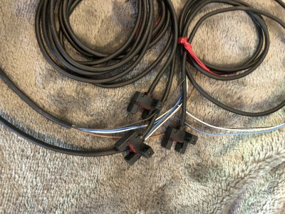
The new optical proximity switches arrived. They are quite tiny and really feel pretty nice.

DOCW5177.JPG

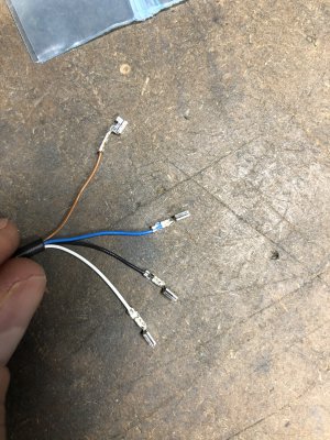
I had a cheap DuPont style pin crimper. It isn't the right tool for these pins, but it worked well enough. The "right" tool for the job would have cost be $450 - kinda crazy.

IMG_9745.JPG

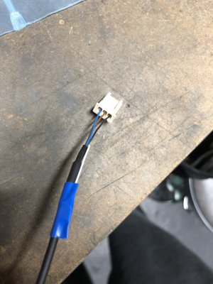
I got the connectors correct and they snapped together perfectly with the original connector.

IMG_9748.JPG

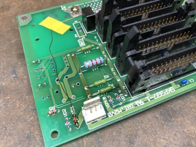
I replaced the 800 ohm resistors (R1, R2, R4) with 1A inline fuses. This gives 24V down the wire without sacrificing the overcurrent protection. I also removed the external 2000 ohm pullup resistors at the servo interface module. After that I plugged in the sensor and got a perfect 23.7V high and 0.7V low. Super happy about this and totally worth trying to get the new sensors working. R3 remained as a resistor since that is how the original board was wired and it is already working so no need to fix what isn't broke.

IMG_9750.JPG

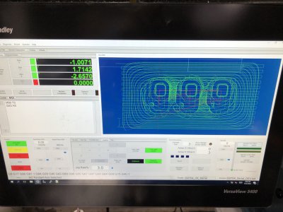
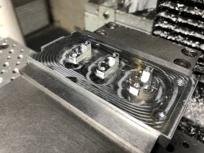
Next up, I programmed up the CNC to make those 3 sensor brackets. I used 5 tools and it took me about 2 hours to program.

IMG_9744.JPG

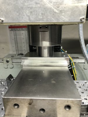
I used a 2x4" piece of aluminum and faced it flat as a fixture. I then lapped another aluminum block against my surface plate to get it flat and superglued them together. The spindle was used to apply down pressure for an hour until it cured. I was concerned about the stability of this method, but it was rock solid.

IMG_9743.JPG

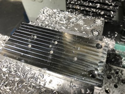
Faced and drilled.

IMG_9751.JPG

Tabs roughed and finished.

IMG_9753.JPG

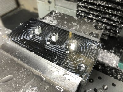
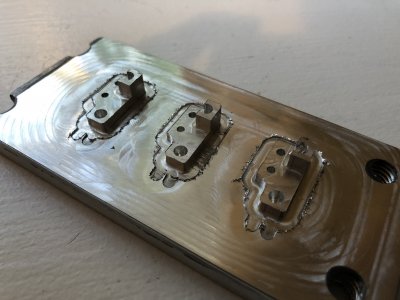
Body was finished at this point. 10 thou of material remains above the superglue for stability.

IMG_9754.JPG

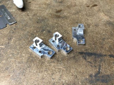
And cut through the remaining foil down to the super glue. The 1/8" endmill is pretty dull and left a bad burr. The parts were easy to clean up and the foil remnant is thrown away. About 3 minutes over my gas stove got the glue hot enough to break the parts loose.

IMG_9757.JPG

Here are the parts, cleaned and deburred.

IMG_9759.JPG

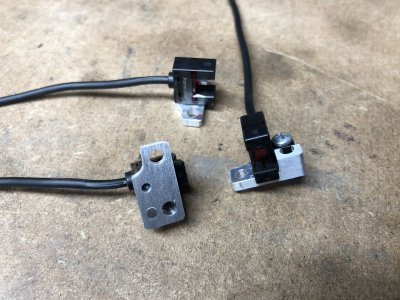
And the sensors installed. These turned out great!

IMG_9760.JPG
 
Last edited:
OK, I lied earlier, there was a bit of machining on this project :)
 
After I got those machined, I was able to install the U axis sensor and T2 sensor without needing to disassemble the arm. Getting the T2 sensor installed was tricky, but I was able to fish the cable through the arm without disassembly.

The T1 sensor is buried deep in the arm and needs disassembly to install. My dad is spending the weekend with me, so I might drag him into him helping me take it apart.

I do have one major hiccup right now. I tested all the sensors before installation and everything worked perfectly. After I got everything buttoned back up though, the U axis sensor was stuck at 3.3V and would switch between 3.3V and 0V when I hit the robot or banged on the table. Like there was a loose connection.

I was able to narrow it down to the X10 connector being plugged in (it was not while I was doing initial testing. The X10 connector services the T1 motor encoder and the T1 homing sensor. There should be absolutely no interaction between this and The U axis sensor on the X40 connector.

I tracked this back even further and found out the sensor work correctly when the T1 motor encoder is unplugged and gets hosed up when the encoder is connected... Not good, there DEFINITELY should not be any interaction between these two devices

I checked the T1 encoder and found the B positive encoder phase is reading 0V steady. All other phases were showing encoder counts. I really hope that the encoder and motor didn't get damaged when I plugged this sensor in.

I did not scope this motor's phases before I connected it to the feedback adapter board. I need to power the motor up again and make sure it is still working. If it is no longer working, then I damaged the encoder when the sensor was attached. Really hoping not.

Not sure why there is any interaction between these devices - need to trace that further. Could be a short on the PCB... I saw weird behavior on this sensor even before replacing it, so I have a feeling this has been an existing problem.

In other news, Rockwell released Studio 5000 V33 PLC programming software this past week. The big news is that it now has native support for my robot's kinematics (including the Z/U screw interaction). I will be migrating to this version and starting to develop the runtime program.

Next steps forward are:
  • Fix the U axis homing sensor & T1 encoder
  • Measure homing angles
  • Develop the robot PLC program
  • Develop an HMI interface to the PLC program
  • Design and machine a pneumatic gripper
 
Last edited:
To keep my thoughts straight, here are the tests I'm going to do to figure out what happened with the T1 Motor / U Home Sensor:
  • Unplug U Home sensor. Does the T1 B phase work?
  • Unplug U Home sensor. Does the motor pass the hookup tests and run OK?
  • If the B phase does not work, does it work on the other motors?
  • With power off, is there any continuity between the T1 motor encoder and the U home sensor?
  • Remove PCB and see if I can trace any problems out.
If I fried the motor, I can try to replace the encoder output driver chip, or get a new motor for $130... Bummer
 
So, it turns out I did fry the motor. I started testing as stated in the previous post and couldn't get the B phase to work anymore. I tried running the motor hookup tests built into the servo drive and they all failed and the drive would fault on E11 (Illegal Hall State). Remember that I had this motor working perfectly a week ago. Scoping my feedback adapter board showed absolute garbage coming out of the hall effect commutation outputs. This is because it cannot correctly decode the signal if the B phase is dead.

I wanted to see if I could figure anything out, so I removed the T1 motor from the underside of the large cast aluminum base. The maintenance manual is very clear about how to do this, but this dummy removed pretty much all the screws but the correct ones. I finally got it out though.

This is the wave generator from a harmonic drive. These are the absolute coolest mechanical devices that I can think of and I've always wanted to hold one. If you are interested, check this wikipedia link out. The ground bearing race visible just below the large steel puck is ground extremely thin and pressed over an elliptical plug connected to the motor shaft. The bearing freely deforms to match this elliptical shape. If I squeeze it on the major axis, the motor shaft will rotate about 90 degrees which is totally wild.
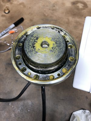
Image111.JPG

Here is the rest of the harmonic drive. The thick ring with the bolts around the perimeter has spline teeth cut on the inside and mates with the flexspline (shown inside with the yellow grease). The flexspline is a thin cup made from fatigue resistant steel with external spline teeth. It has 2 fewer teeth than the circular spline and connects to the load (robot arm). When the wave generator is inserted into the flexspline (that's in the polished area free from grease), the flexspline deforms into an ellipse. As the input shaft is rotated, the wave generator creates a meshing action between the flexspline and the circular spine along the major axis of the ellipse. The spline advances two teeth forward for every revolution of the input shaft, giving extremely high reduction ratios. Since the meshing action is wedge shaped sliding rather than rolling, the gearbox can be made with near zero backlash.
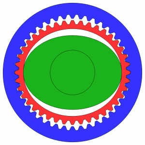
HarmonicDriveAni.gif

These are used in robotics, planes, the International Space Station, and the wheels of the Apollo lunar rover. Cool stuff.
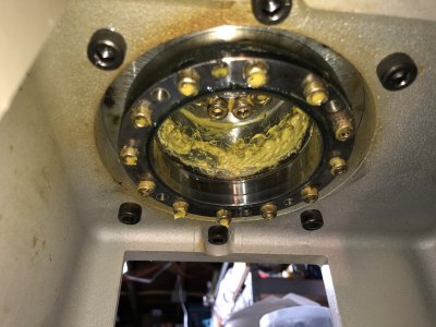
Image113.JPG

I tightly wrapped the wave generator in plastic wrap to keep it clean and placed masking paper on my workbench to create a clean workspace.
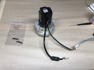
Image116.JPG

This is the output section of the Yaskawa encoder. The JL-041A chip on the left is their proprietary ASIC which multiplexes the encoder signal and made my life so difficult. The chip on the right is a Texas Instruments AM26C31I Quad Differential Line Driver. This chip buffers the signals coming from the JL-041A and creates an inverted pair of signals to be transmitted on twisted pair wire over substantial distances. I was really hoping at this point that any damage would be limited to this chip.
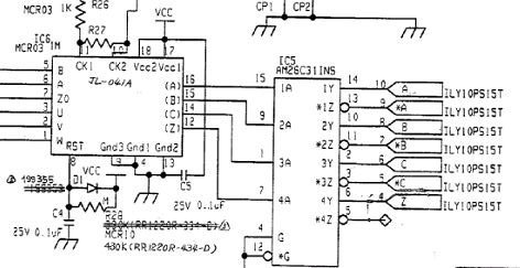
Image120.JPG

Using some 30AWG magnet wire, I attached to various pins on the chips. In particular, I got pin 15 of the JL-041A (B phase output) and Pin 9 of the AM26C31I (B phase input). I was really hoping that this signal would be intact. If not then the JL-041A was dead and I'd have to toss the motor. I also soldered to pins 10 and 11 of the AM26C31I which are the buffered pair of signals that should look like the B phase (except pin 11 should be inverted).
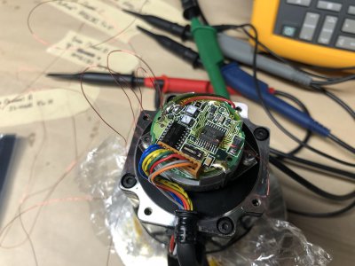
Image128.JPG

Here's the scope probes. All of them referenced the power supply common.
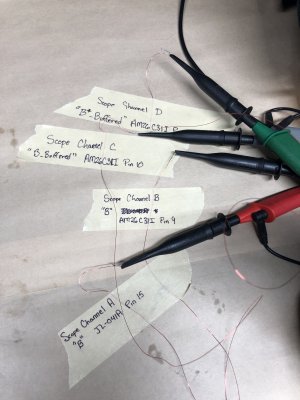
Image125.JPG

And here is what I got on the scope. As expected, Channel C (B phase buffered output - noninverted) is dead and sits at 0V. The good news is that Channels A & B are showing a perfect signal of B so the rest of the encoder is OK. Notice how Channel D (B phase buffered output - inverted) is the opposite of A & B. This is for noise immunity when transmitted in a twisted pair with channel C.
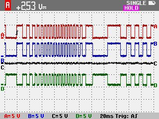
Image133.jpg

I got pretty excited at this point. When I designed my feedback adapter boards, I copied this exact chip as the output driver. I have spare chips to make one additional feedback board.
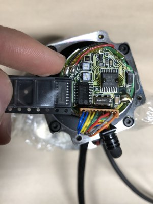
Image119.JPG

The big challenge is that just below this this circuit board is the precision etched glass phototransmissive disc that the encoder reads. Any contamination at all could ruin the encoder. There are also parts hanging from the bottom of this circuit board so I couldn't use the hot air gun to remove the chip. I opted to mechanically cut each leg of the IC with a pair of sharp diagonal snips. I then used my soldering iron to remove the remnant of the leg from the pads. I accounted for each of them so I didn't leave junk in the encoder. I used some nice solder wick to clean the pads and remove this goop that they used to secure the chips to the board.
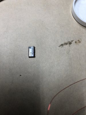
Image129.JPG

Finally I placed my new chip on the board and hand soldered it in place with the thinnest solder I own. It doesn't look very pretty because I was using a soldering iron and not paste and a hot air gun, but whatever, the joints are good. I added the test leads back on.
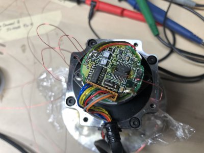
Image131.JPG

And after powering it back up, all the signals came through perfectly! I can't believe I was able to get this fixed. I think this is back to 100% functional. Channels C & D get fed directly into my feedback adapter board. I removed all the test leads and sealed the encoder back up.
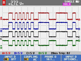
Image134.jpg

I will not reinstall the motor until I can figure out why it got fried in the first place. I am expecting to find a short between the B phase of the encoder output and the output of the U axis home sensor output. I'm guessing the old sensor was shorting but since it was a sinking sensor (and it only sank 6mA) it did not damage the encoder. I think that when I put in the new optical homing sensor on the U axis, it can now source 24V at 100mA which went directly into the AM26C31I driver output and fried the chip inside.

I'll do some continuity checks next and try to identify the source of the issue. It is probably on the robot PCB, but it could also be in the interconnect cable or at my terminal blocks.

Whew - Mike
 
Last edited:
I am no electronics person by any means. Give me voltage.

But I am enjoying following your thread and the analysis work you are doing. I love analysis and the logic behind it. Looking at these pictures of the motor, I did not understand the scale until I saw your finger holding the new chip next to the old over the motor. I don't think my fat fingers would do well with this.

Yeah the encoder is tiny for sure. The first time I messed with the encoder (back on page 2 of this thread), I would soldering in the dark while kneeling on top of the table with the robot. I don't know how I got that done. At least this time I was on a brightly lit workbench!

Thanks for following along and writing back! I enjoy sharing this project and it gives me a kick to keep moving forward.
 
Back
Top