Mike's SCARA Robot

Was able to confirm. There is a dead short between X11-3 (Encoder signal 1B) and X42-1 (Sensor signal 4HOME). This is what fried the encoder. This short remains when the SIGNAL cable is unplugged from the back of the robot, ruling out a short in the cable or at the terminal blocks where I did all my wiring.

The short disappears when X10-X50 are unplugged from the robot SKP337-1 PCB ruling out any quantum tunneling/magical effects of electrons jumping between different cable harnesses. Pretty certain that the short is somewhere on the PCB. Will update when I learn more.
 
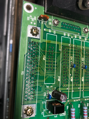
I told you I am no expert when it comes to electronics, but from this image I pulled from an earlier post of yours. It looks like the burn mark goes all the way from X50 to X10 crossing over several circuit paths. Could the carbon from what I am calling the burn line cause it to short across different circuits?

1602098607735.png
 
I told you I am no expert when it comes to electronics, but from this image I pulled from an earlier post of yours. It looks like the burn mark goes all the way from X50 to X10 crossing over several circuit paths. Could the carbon from what I am calling the burn line cause it to short across different circuits?

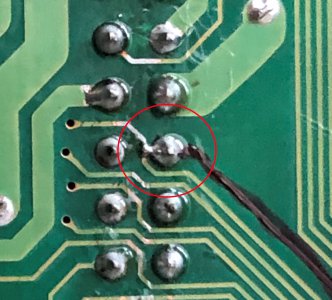
Well I found the issue. It was related to this blown trace but not exactly as you described. I scrubbed all that crap off the board with isopropyl alcohol when I first repaired it, however when I soldered the connectors back on, I ran into trouble with the soldermask rubbing off easily. This left a glob of solder connected to the X40-20 pin and it jumped to the trace sneaking next to it. This trace was the X10-5 signal which went to the T1 B encoder phase. The black line is sharpie I used to follow the trace all around the board.

Image135 (2).JPG

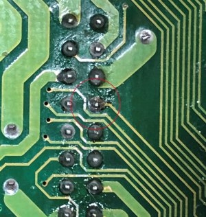
A quick cleanup with solder wick left this connection completely repaired.

Image137 (3).JPG

I tested the continuity between the sensor and the T1 encoder pin and no longer had connection. While testing continuity, I shorted this connection again with a screwdriver and got a beep. I am confident this was the issue. I'll triple check this and then reconnect the motor and try to get it working again. I'm hopeful the encoder repair worked. I also hope the U axis homing photosensor is OK, but I didn't see any signs of damage before so I am not too worried.
 
Glad that you found the issue. With the circuits being so small, it is great because you can put a lot into a very small area. But on the other side of it, it is really easy to cause impacts to local circuits.
Thanks for sharing your findings.
 
Was able to test the T1 motor and it ran great. The harmonic drive made a few funny sounds while the grease settled in and now it is nice and quiet again.

Have not tested the homing sensor, but I don't expect to have any issues.

The last two mechanical tasks are to install the T1 homing sensor inside the shoulder (T1 joint) and to measure the zero angle offsets with a dial indicator. Then time to start programming.
 
Hi all, hope everyone had a great weekend. Had my dad come visit and coerced him into helping me finish the T1 home sensor installation. The maintenance manual gave a pretty good description of how to do this, and I've attached the relevant pages here.
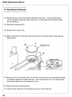
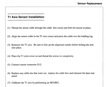
1602517590667.png

1602517608756.png

The bolts well very tight and required a substantial cheater bar to break them loose. The arm lifts off a boss on the shoulder joint and can be laid on the table without undoing the cable harness. It weighed probably 60lbs.
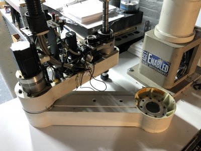
Image138.JPG

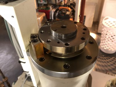
The shoulder joint was pretty neat to see and was pristine in condition. It still has a thin film of rust preventative all over the steel components. You can see the multi slotted homing code wheel in this shot. I was considering replacing this with a single slot variant, however I don't think it is worth the effort. I will manually position the arm at the homing location before startup, just as the operation manual for this robot with the original control describes.

Since the arm can be travel limited with special bolts for safety reasons, it is possible that a single homing location may be inaccessible if the travel was limited.
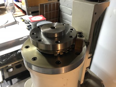
Image139.JPG

Here's the other side.

Image140.JPG

From the top, you can see the two sector blocks on the right side which act as hard stops for the T1 arm motion. This arm can move incredibly quickly and weighs quite a lot. An impact with these hard stops would be very violent. The blocks have roughly 1/4" firm rubber pads (amber colored) glued to their faces to act as bumpers to absorb impact energy.
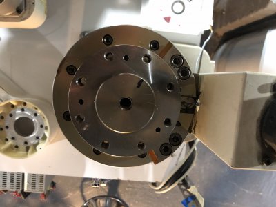
Image141.JPG

Here is the original homing sensor as-installed.
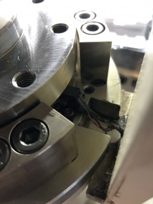
Image142.JPG

And my new one. The clearances between my mounting bracket and the code wheel are tight, but everything worked perfectly.
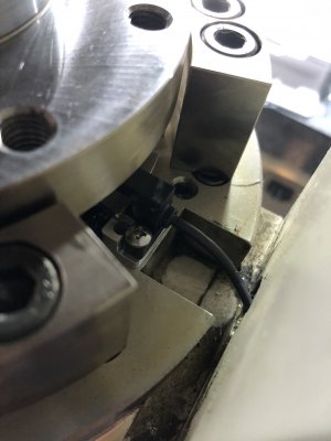
Image143.JPG

Now that I have all the motors and homing sensors working, there is no need to keep the covers removed. I gave them a good wash and reinstalled.
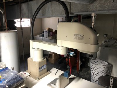
Image145.JPG

Here's the lower cover. I think the gridded ribbing on the first arm link (left side of pic) is pretty cool.
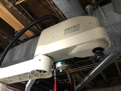
Image146.JPG

With all 4 sensors installed, I was able to test the homing and it is working great. As mentioned above, the T1 and T2 axes need to be manipulated to place them close to the home location. The homing sequence can then be run from there.

You can see the dial indicator set up to measure the homing angles. I need to find the center of the aluminum robot base and draw a perpendicular line across the table. The dial indicator should be close to centered over this line. The more accurately I can measure the homing angles, the more accurately the robot will position in cartesian coordinates after the transform, especially at the edges of travel.

I started the actual runtime program for this robot as well as the HMI screens. The program is a state machine with the transitions between states handling power on, homing, power off, hard stop, and fault reset. The 3 states I chose are Stopped (powered off), Running (able to perform motion, may or may not be moving), and Faulted (something went wrong). The transitions are Starting (power on and homing), Stopping (stop motion and power off), Faulting (hard stop motion and power off), and Resetting (clear faults).

A super quick test of the code yielded some bugs (as expected), so I'll need to spend a little time troubleshooting it. I also want to spin up a computer to act as the HMI terminal for this robot program.
 
Congrats, that is an amazing piece of equipment.

Do you have a plan for it, or is this work you are doing currently the plan? Which there is nothing wrong with the learning process that you are going through. Maybe a second purpose will arise after the learning process.
 
Congrats, that is an amazing piece of equipment.

Do you have a plan for it, or is this work you are doing currently the plan? Which there is nothing wrong with the learning process that you are going through. Maybe a second purpose will arise after the learning process.

Thanks! Getting close!

Honestly no, I don't have a plan for it. I love robotics and this showed up at the right time (quarantine) and was cheap. I plan on writing a nice operating program and interface for it, and then making some simple programs. Here were a few ideas I had (open to more!):
  • Attach a dry erase marker and draw shapes on a whiteboard
  • Pick and place assembly of small lego cars (got some pieces from my dad when he visited for this purpose)
  • Pick and place assembly of something? using a gripper I want to design and machine
  • 3D printing by attaching a hot end extruder. It would have a very large workspace.
  • Lightweight machining????, maybe, probably not though.
  • Auto tool changer for my CNC mill. Integrate with Mach 4 using Modbus TCP. This would semi-permanently attach it to the machine, so I'd want to be sure I was done playing with it by that time.
  • Fun educational demo for a local high school shop class?
 
I can understand the primary purpose of just learning how it works and can I fix it, followed by programing it for what ever. That would have been enough. I could see this as a tool changer but would be concerned with chips or coolant getting at the electronics. Maybe it is waterproof but didn't look like it.

I love the mechanics of the arm. Beyond what you have already done, which as I said would be a satisfying project alone, it really doesn't matter what you do with it. That is along as you are enjoying yourself.

I have designed and built machines many times over the years. Could have gone and bought one but always like the challenges and felt I could do it better. For me, it has to look like it came out of a factory and performs. Once I get past that, it is more of what is next.

But now that I think about it. That could be a great way to feed cases into my annealer that I built or some other reloading process. Maybe take the measured powder from my Sartorius lab scale that I use for my competition loads and drop it into the case for me. Not necessary but would be cool.
 
Back
Top