-
Welcome back Guest! Did you know you can mentor other members here at H-M? If not, please check out our Relaunch of Hobby Machinist Mentoring Program!
You are using an out of date browser. It may not display this or other websites correctly.
You should upgrade or use an alternative browser.
You should upgrade or use an alternative browser.
Help On How To Set Up And Make This Item.
- Thread starter Ken_Shea
- Start date
- Joined
- Oct 29, 2014
- Messages
- 354
- Joined
- Jan 21, 2015
- Messages
- 9
I'm following this thread, even though I know absolutely nothing about machining.
For example...if i were doing it, I'd need about 6 months lead time and ton of Dremel bits...
The knowledge on this board is very impressive. Except in my posts.
Tim
For example...if i were doing it, I'd need about 6 months lead time and ton of Dremel bits...
The knowledge on this board is very impressive. Except in my posts.
Tim
- Joined
- Dec 8, 2013
- Messages
- 2,651
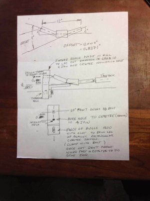
If you milled a 2 degree bevel on the angle iron you could bolt the center section to it.Ken, here's a rough sketch of what I was trying to explain last night. Forgive the table cad.
Think this would work. You'd need to machine a block to locate and offset the one end to get your angles. Ream or bore a hole that you can latter use to centre the fixture in the four jaw, step over 0.8371 inches, drill and thread a second hole for the dead centre. The centre could be a bolt turned to a point. The spacing as you know is critical, for the part 12 inches long the offset would be 0.8371 inches. The slotted angle iron would be brought up and squared against the centre section and clamped to act as a lathe dog. Once set on the first turning leave it fixed and it will index the second one in plane with the first.
The tail stock has to be centred or you will get a tapered profile.
Hope this helps explain last nights ramblings.
Greg
My suggestion is to get a set of soft jaws for your 4 jaw chuck. Then take them to the mill and on two mill you two degrees. Obviously one will be opposite of the other so they match up. The other two are left normal. Then you can clamp your part turn it and then flip it and repeat. Bam done. Center can be used.
Note: it will be rough interrupted turning a center is recommended. But it can be done without but it will take longer.
You could machine a step in the jaws or not your choice.
Also this would insure that both were nice and lined up.
Note: it will be rough interrupted turning a center is recommended. But it can be done without but it will take longer.
You could machine a step in the jaws or not your choice.
Also this would insure that both were nice and lined up.
- Joined
- Dec 8, 2013
- Messages
- 2,651
I like this, but I think he needs 4 degrees on the jaws. Also a 4 degree bevel on the end of the part would eliminate any need for a step in the jaw.My suggestion is to get a set of soft jaws for your 4 jaw chuck. Then take them to the mill and on two mill you two degrees. Obviously one will be opposite of the other so they match up. The other two are left normal. Then you can clamp your part turn it and then flip it and repeat. Bam done. Center can be used.
Note: it will be rough interrupted turning a center is recommended. But it can be done without but it will take longer.
You could machine a step in the jaws or not your choice.
Also this would insure that both were nice and lined up.
- Joined
- Mar 25, 2013
- Messages
- 4,615
My suggestion is to get a set of soft jaws for your 4 jaw chuck. Then take them to the mill and on two mill you two degrees. Obviously one will be opposite of the other so they match up. The other two are left normal. Then you can clamp your part turn it and then flip it and repeat. Bam done. Center can be used.
Note: it will be rough interrupted turning a center is recommended. But it can be done without but it will take longer.
You could machine a step in the jaws or not your choice.
Also this would insure that both were nice and lined up.
I assume you are talking about clamping the part by the square center section. This would work great if the chuck/spindle bore can accommodate the other end of the part. If so, this would be the simplest most elegant idea yet.
Can I delete my ugly drawing now?
R
Last edited:
Not yetCan I delete my ugly drawing now?
The only soft jaws I've seen are bolted on, my 4or 3 jaw has no provisions for bolting on any soft jaw
Also thinking it be very iffy as to whether or not the bore would accommodate the end, it's a rather shallow angle so maybe, just maybe
Tomorrow I'll take a quick look see with this suggestion in mind with the soft jaws being clamped in place using the fixed jaws.
Even if it could be accomplished how in the world would one dial it in after swaping ends?
Woe is me, deep dark depression, excessive misery.
- Joined
- Dec 8, 2013
- Messages
- 2,651
I think the idea is to grip the end of the piece with the soft jaws, with the jaws offset . That's why you would need to grind 4 degree angles into them.Not yet
The only soft jaws I've seen are bolted on, my 4or 3 jaw has no provisions for bolting on any soft jaw
Also thinking it be very iffy as to whether or not the bore would accommodate the end, it's a rather shallow angle so maybe, just maybe
Tomorrow I'll take a quick look see with this suggestion in mind with the soft jaws being clamped in place using the fixed jaws.
Even if it could be accomplished how in the world would one dial it in after swaping ends?
Woe is me, deep dark depression, excessive misery.
- Joined
- Mar 25, 2013
- Messages
- 4,615
What degree of accuracy is required here and which tolerances are critical? With the angles ground into the jaws you should have good precision (repeat-ability) for the angle when flipping the work. This will make it symmetric even if the angle is off slightly from 2 deg. If you dial in the straight jaws and are dead center to the rectangular part you should be very close if you leave one straight jaw and one angled jaw in place when flipping the work. I would use a center in the tailstock as noted previously.
Some of this discussion depends on how many of these you are going to produce and how much the part is worth. Is it worth investing in a high end chuck with removable soft jaws?
I still think this solution is the way to go, in spite of my crazy diagram.
One question that has not come up: does the FAA need to certify this part for flight use?
R


