Help On How To Set Up And Make This Item.

wouldnt it be easier to mill two parallel flats on each end of the bar set off by 2 degrees to the centerline of the bar?
 
One question that has not come up: does the FAA need to certify this part for flight use?

Quantity = 1 and no FAA certification is required.

The degree of dihedral is not so critical as it is a compromise to begin with, that both shafts have equal dihedral would be important, also that the shafts extend from the center block in a perfectly straight manner to each other would also be important.
It will be yet necessary to determine what those tolerance would be but it will be tight, for that matter even the final dimensions have to be determined. Once the final part machined I would have it sent out for measurement. Just .001 out of straight projected out 12.5 foot adds up.

This component is currently manufactured by a helicopter kit manufacturer as part of a factory assembled rotor head assembly and do not believe available separately.

It will be interesting to see how this goes and to be honest I'm not the least bit looking forward to it.

Unless another simpler solution is brought forth I'm going to start with JimDawsaon's suggestion in post #2 as it seems to offer the least amount of setup.

You guys have sure gave my mind a work out, can't say I'm all that grateful for that :) but your input has been invaluable.

Thank you again.

Ken
 
Got it. Yes this was a very interesting discussion.
So a 3 piece solution? I would be more worried about the accuracy of drilling the holes at 2 deg and threading the shafts with any accuracy. That will definitely get you off a couple of thou. I still think post 76 would be a very accurate and simple solution. Shars has some pretty cheap 4 jaw chucks that you could get soft jaws for.
Keep us posted if you proceed!
R
 
So a 3 piece solution?
It will be the three sections in one piece but not separate sections.

Here is a picture of the part with both the smaller old style and the newer larger version being discussed here.
It is shown upside down.

MRS-2.jpg
 
I'm not sure on the angle so I just said 2 degrees but if you don't have removable jaws on your chuck making two shims sort or almost aluminum angle blocks of the appropriate angle with bolt holes that allow you to bolt on to the rectangle portion would work. To get it centered just used an indicator and center it as you would and square part.
Now if you don't have a big enough lathe well then that would be a problem but I often forget about that because my lathe is not huge but big for its size.


Now you don't have to listen to me and nobody has to but if that helicopter or plane goes down due to the three piece setup your are doing I know I would feel allot of guilt because i didn't do it right in the first place.

I also think making it from three pieces will be harder to get the same level of accuracy.
 
  • Like
Reactions: rwm
Thanks for the input lanagos,
They say the third time is a charm and this may well be the fourth :) ......it is a single solid, one piece part.

Ken
 
I have been staring at this for some time, and a question popped up. Would it be possible to have a block on each end of the spindles to put your centers in, then use a 4 jaw chuck to set the offset and turn at the tailstock end? I don't have cad, but it would look something like this III-----III-----III, where the III equates to the rectangular and the ---- represents the spindles. Then when the pieces are machined, the end centering blocks can be cut off. Just thinkin'.
 
I have been staring at this for some time, and a question popped up. Would it be possible to have a block on each end of the spindles to put your centers in, then use a 4 jaw chuck to set the offset and turn at the tailstock end? I don't have cad, but it would look something like this III-----III-----III, where the III equates to the rectangular and the ---- represents the spindles. Then when the pieces are machined, the end centering blocks can be cut off. Just thinkin'.
That's pretty much what I tried to describe. You'd mill the blocks at a 4 degree angle to the spindles so that the chuck could grip them squarely.
 
Of course I've got to see how it works out with my first attempt using Jim Dawsons suggestion, I've a good feeling about it.
The added blocks are a good idea and could prove beneficial if the first method does not, my biggest concern using a chuck is swapping ends while insuring an exact alignment with both ends, maybe in actual practice it won't be a problem but I am imagining that it will right now.

Thanks
Ken
.
 
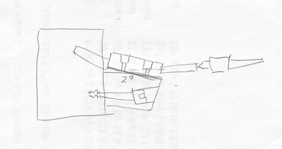
Mount a block on a face plate so that it has a face, offset 2° with four tapped holes in it to match the holes on the device. mount the piece on the block, put a center in one horn and turn it. Remove the device and put the other horn on the center and turn it.

Please excuse my drafting dept. they're on break.

1 block.jpg

Tom
 
Back
Top