-
Welcome back Guest! Did you know you can mentor other members here at H-M? If not, please check out our Relaunch of Hobby Machinist Mentoring Program!
You are using an out of date browser. It may not display this or other websites correctly.
You should upgrade or use an alternative browser.
You should upgrade or use an alternative browser.
Cromwell S800 Mk3 lathe
- Thread starter RodF
- Start date
- Joined
- Apr 12, 2011
- Messages
- 3,480
Thanks Randy
Congratulations on your 1000 posts.
Rod
:laughinghard: Rod, I hadn't even noticed. Thanks for pointing that out. Keep up the good work, sure looks like you know what you are doing. Thank you for sharing your fun.
- Joined
- Apr 16, 2014
- Messages
- 142
Work has been interfering with the lathe project over the last couple of weeks and it is too cold in the workshop at night.
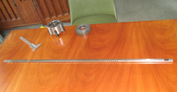
6mm keyway broach arrived from China. Despite protection in a wooden box it still arrived broken. I have had a lot of items from international destinations and this is the first to be damaged. All is well though as it is a draw broach and cuts the full depth in one pass. There is still plenty of material to modify it for my broach press.
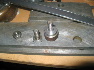
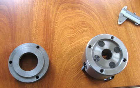
Independent 4 jaw chuck also arrived. This will also need to be modified to fit the adapter plate.
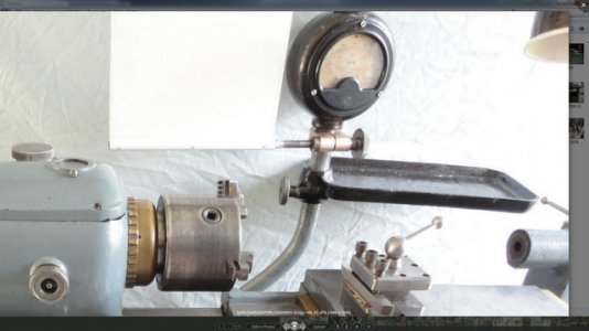
One of my colleagues at work gave me an old meter which I can adapt to an RPM meter. Will mount a new voltmeter unit inside the housing and get new scale artwork.
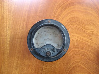
Original had dual scale for the back gear speed. I will duplicate the original cast housing with a 3D printed part.


6mm keyway broach arrived from China. Despite protection in a wooden box it still arrived broken. I have had a lot of items from international destinations and this is the first to be damaged. All is well though as it is a draw broach and cuts the full depth in one pass. There is still plenty of material to modify it for my broach press.

Independent 4 jaw chuck also arrived. This will also need to be modified to fit the adapter plate.

One of my colleagues at work gave me an old meter which I can adapt to an RPM meter. Will mount a new voltmeter unit inside the housing and get new scale artwork.

Original had dual scale for the back gear speed. I will duplicate the original cast housing with a 3D printed part.


- Joined
- Apr 16, 2014
- Messages
- 142
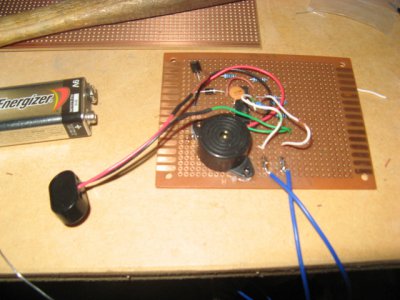
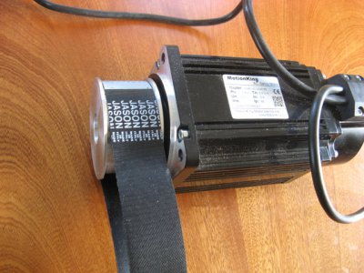
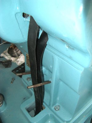
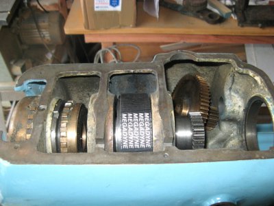
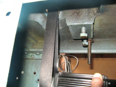
Took the spindle off again and fitted the continuous belt. As you can see it will need an idler pulley to guide it through the back belt aperture. Looks like there is plenty of length in the belt and also may not need an idler at the motor end. Have also been working on the electronics for the servo controller. Not especially difficult but it has been quite time consuming.




- Joined
- Apr 16, 2014
- Messages
- 142
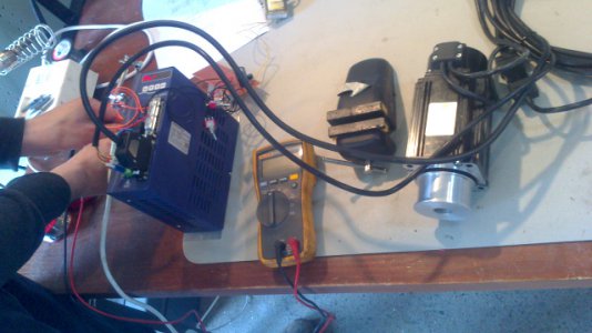
Progress has slowed due to work commitments, however I have some time off now. Got the servo running today, it seems to have plenty of low speed power and runs very smoothly up to full rpm. Got one of my friends, an electronics engineer to look over it before I powered it up. Still a little tuning to be done.
