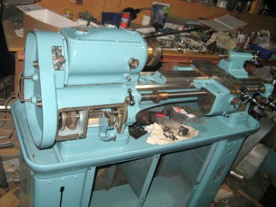
Cromwell S800 Mk3 lathe

Got the spindle in and the gear on the back of it. That meant I could mount the back gear housing. I am keen to get the servo running about now, so I can start on the motor mount. I have some ideas for duplicating the original control system and also a rpm gauge. This is where the 3D printer will be useful.
IMG_2506.JPG

IMG_2506.JPG
 
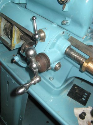
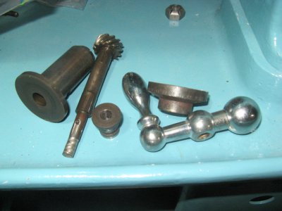
Sorted out a problem I had with the left hand apron driver. As I got it the shaft was bent almost 45 degrees. I straightened it using force and heat but it was still seized solid. Tonight I finally got it apart and can now have the dial chromed along with a few other parts.

Most of my time on the Cromwell project recently has been researching the servo controller setup. The servo controller needs to be operated in velocity mode which needs an analogue input from a differential mode OpAmp. The driver instructions are pretty good for a Chinese product, but it has been a fairly steep learning curve for someone like me who hasn't had a lot of experience with this stuff. However I think I have it worked out now (but will run it past a qualified electronics engineer).

IMG_2517.JPGIMG_2520.JPG

IMG_2517.JPG IMG_2520.JPG
 
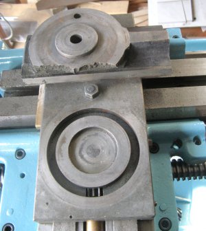
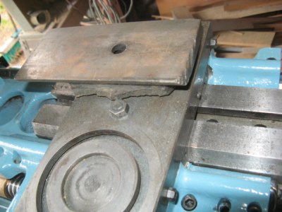
Unfortunately the base of the top slide is damaged. There is enough left of the T nut hole for nut to have some clamping effect though and I think that will improve with some sort of rebuilding. My thoughts at this stage are to shape a piece of steel to fit as well as I can get it then screw it to the slide base and fill the gaps with silver solder. I do have a stick welder and presumably could do something with the correct welding rods. Any thoughts on this would be appreciated.

IMG_2521.JPG

IMG_2521.JPG
 
Yep, it certainly has been abused. Hopefully it will have an easier life from now on. Still I think there is enough metal left for some clamping force and hopefully I can effect some cosmetic improvement as well. I will leave the damage on the end as it will be mostly covered by the slide.

IMG_2524.JPG

IMG_2524.JPG
 
Last edited:
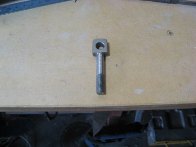
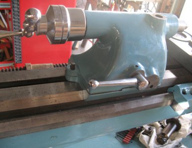
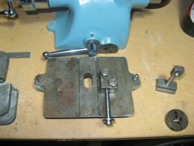
Made the connector bolt for the T nut and lock arm on the tail stock. Tested it and it has a really nice action. Now to make the adjustment screw. This is the early style of tail stock, the later type looks to have more throw and better adjustment method.

IMG_2527.JPGIMG_2529.JPG

IMG_2527.JPG IMG_2529.JPG
 
Made an adjustment screw for the tailstock. Overcooked the die tightening so it is a bit loose so will probably make another one. Will cut a slot for screw driver and lock it with a custom washer. The front stud also needs replacing.IMG_2536.JPG

IMG_2536.JPG
 
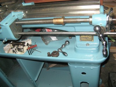
Got a length of 5/8" silver steel to make the replacement cross slide drive shaft. It is a nice fit, I need to cut a 1/8" slot in it for the drive key.

IMG_2538.JPG

IMG_2538.JPG
 
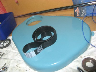
The drive belt I ordered turned up today, so it is back to drive plan A. This will involve at least one idler and I think a new motor pulley. The belt is manufactured as a continuous loop, not spliced so it should be strong and vibration free.
IMG_2540.JPG

IMG_2540.JPG
 
Back
Top