Bob Shores Eagle Hit/Miss Engine Build Thread

How about making it out of stainless. Here is tubing .038 I.D. x .094 O.D.

It is just a tad over what you wanted for the ID but close. I did not find brass or aluminnum close to the sizes you need. But I did not look real hard either.

For the flange at the barb end just solder on some extra to machine for that end.

You may even be able to solder your brass tubes together to get what you want. I would not trust any adhesive.

Ah! You might just be my hero! I thought I had looked at everything mcmaster had, but they must have fallen right out of my search region every time.

I can use a bigger needle easy enough, and turning down the OD a few thou shouldn't be a problem either.

Thanks!
 
Part 34: The piston & Ring part 1!

The plans call for a CI piston and a ring, though the instructions call it unnecessary. It says to start with a 1" piece of ~3" long cast iron, instead I have 1 1/2" CI about a foot long. Oh well, I did a little stickout :) Of course, I started by facing it.

IMG_20200701_140838.jpg

The plans call for making the piston and rings out of the same piece of material, starting with turning the OD down. My cylinder ended up a little large (874 instead of 870), so we're making a piston to match. I messed up F&S a little in my roughing and cooked one of my HSS bits, but a quick regrind and a slight decrease in speed fixed it :)
IMG_20200701_142742.jpg

I lapped it with some 320 and some 500 grit sandpaper (though my finish with the HSS was fabulous anyway), and go the cylinder fit pretty darn good. It actually took about 2 minutes for the cylinder to tip around from this position, as the far side is the heavy one. It slowly moved for a while in the time I took to take this shot.

IMG_20200701_143345.jpg

You'll see on the plans sheet later, but this part required 3 different bores, at specific depths. The first is just a 5/16 drill bit. I came up with this mag-base dial indicator + Kant clamp today since I had to measure the depth pretty accurately.

IMG_20200701_144617.jpg


After that, I bored the other 2 out. The drill is the connecting rod clearance, then there is the 'skirt' area, and finally a section in which to cut the rings from. A dial indicator on my bed plus some power feed got the other two done in a short time!

IMG_20200701_150228.jpg


This is what the plans call for on the piston. The left 750 is a piece for workholding, and you can see the other 3 diameters.

IMG_20200701_151355.jpg

I parted off the rings with 2 separate tools. The first left a little bit of a leftover, just too much to remove by bending it. The 2nd try made it into the chip pan after jumping out of my 'catch' box. The 3rd is on the right. It ended up with ~1 thou of leftover on it, but handling it for a second fixed it! I'm hopeful that between these two we can make a ring! The plans suggest using a 3-8 thou cutoff wheel to cut the slot. I have zero idea where to get something like that, so I'll have to be creative trying to cut it. Then, it wants a magnet + some heat-treat to make it a little springier. I'll have to get creative with that as well!

IMG_20200701_152740.jpg

Back to the lathe I used my tinsy grooving tool to cut the grove for the ring. This tool is micro, but is surprisingly robust!

IMG_20200701_153613.jpg

I did a bit of work to have the part to hold on the piston, then called it a day. I still have to drill the wrist pin hole and connecting rod slot, then I cut/grind that part off. BUT, that is tomorrow's problem :)

IMG_20200701_154933.jpg
 
Part 35: The end of the Piston, Rings, and Wrist Pin

Ok, so the first task was to cross-drill for the wrist pin 3/16", then ream it. I used the DRO to locate it. This was obviously easy enough!
IMG_20200702_132347.jpg

Next I had to flip it upwards to mill out the relief for the rod to go around the wrist pin. I used a 3/16" drill bit and my calipers to get it as straight as possible here. The connecting rod is only 1/4", so the 5/16" slot has a little bit of leeway.
IMG_20200702_132949.jpg

I centered the mill best I could with the coax indicator. I'm sub-1/2 thou as best as I can tell.

IMG_20200702_133309.jpg

The plans say to cut this ".425" deep, which didn't really make sense. Based on the dimensions, I couldn't find any reference-point to measure that off of that either wouldn't do anything, or would leave only 10 thou of material at the end of the piston. I DID note that the drawing still had the drill-bit circle there, so I milled until I was just about bottomed out in the drill bit. The plans ALSO call for the endmill to move .175 off center, which seemed excessive to me as well. The end of the connecting rod is 3/8" (I might thin that out if necessary!), and that would make the slot .662. I instead went .155, which left a slight bit of material before it got into the skirt. I didn't really want to cut into the skirt, which .175 gets you to at least rubbing.

IMG_20200702_134629.jpg

Finally, I turned the front flat. I didn't end up having to use this arbor-part for anything, so it ended up being just a waste of ~1" of cast iron! I lined the jaws with an aluminum sheet stock that I had.

IMG_20200702_135107.jpg

AND the piston is complete! Sitting on the two ring-candidates.

IMG_20200702_135813.jpg

I was fortunate and was able to peel the extra material off of the 1 ring, and using a bit of 500 grit paper got it flattened. I was happy to have 2 tries at getting the ring right :) The first I used a set of angle cutters, and a ~50 thou piece broke off. I went through the whole process, and actually got a ring I was reasonably happy with, though it had a large gap. SO, I decided to try making the 2nd one. I used a slightly different technique with the angle cutters (I cut at 90 degrees to the ring, rather than parallel), and very little broke out!

IMG_20200702_141548.jpg


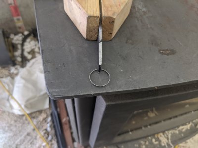
The instructions suggest using a magnet to place the ring on, using a piece of material to 'split' it open a little, then heating the end with a lighter until blue. I didn't have a magnet that I dislike enough to use the flame on it, so I did this. I used a washer of the right thickness to hold the ring open, and this piece of metal to hold it flat. About 20 seconds of flame turned it nice and blue!
IMG_20200702_142537.jpgIMG_20200702_142543.jpg


And installed!
IMG_20200702_142646.jpg

Finally, when I was at Ace I found a 3/16" ground pin, 1" long. I need ~.825 (I ended up at .850, but it doesn't hit the cylinder walls), so I hit it with the grinder to get it to length.

IMG_20200702_143324.jpg

And that was it for the day! I realized I used the piece of stock I wanted to use for the connecting rod on a different project, so I have to order material! I have some brass and aluminum on the way, I haven't decided what I want yet. They won't come until next weekend, so it might end up being the last item holding me up :)
 

Attachments

  • IMG_20200702_141211.jpg
    IMG_20200702_141211.jpg
    3.4 MB · Views: 7
Part 36: Carburetor!

Alright, thanks to flyinfool, I was able to get some hollow tube that would work! I tried a few times to turn it down, but even with tail-stock support I got too much deflection to cut it consistently. I opted to just drill the carb out a little and use it at the .094. Also fortunately, I found a .040 needle, which surprisingly fit in the .038" hole in the tube, which surprised but delighted me!

First, I threaded the end. Despite being a little large, the tap had no problem. Later, I'd have to tighten the die up a little and run it a few times, but this was easy enough.IMG_20200703_105154.jpg

Next, I drilled a #67 through the tube. I used the DRO to find center, and sort guessed as to the location. I have the ability to adjust this with the barbed section, so it isn't critical.
IMG_20200703_111828.jpg

IMG_20200703_111831.jpg

And the needle fits!

IMG_20200703_112542.jpg

Next, I have to make the needle adjustment knob. This took a couple of tries, as my newly acquired #60 bits from Ace have a habit of breaking for no reason ;/ I drilled ~400 thou with a #50 that gets tapped 2-56, and drilled a little further with a #60 for the needle.
IMG_20200703_135438.jpg

Then, I did a little knurling. I have a Pen Tool Scissor knurler that leaves great knurls in everything I've tried so far.
IMG_20200703_140510.jpg

I turned down this section for appearance sake.
IMG_20200703_140843.jpg

Then parted, flipped, and shaped the backside. This just so happened to be about as small as I could hold with my 6 jaw!IMG_20200703_141234.jpg
As i mentioned earlier, I ended up having to tighten the die a few times to get it to cut enough for the brass knob to fit.
IMG_20200703_142738.jpg

And all the parts together! I have to get a spring for it (I think I found a part of one I made earlier in the project that will work. I am putting off building the barb until my fuel hose shows up, so I have a little more assembly/Loctite 609 work to do.

IMG_20200703_143624.jpg
 
I would still not use adhesive for the barb or attaching the needle to the knob, I would solder them so you know it is permanent.
For small stuff like this I have had great luck with HI Force 44 solder and flux from Brownells. It is a siver bearing solder that is stronger than electrical or plumbing solder, not as strong as true silver solder. But it still melts and flows with a good soldering iron or a propane torch. Be careful even propane can melt these tiny parts pretty quick.
 
Why's that? I have had pretty good luck with the Loctite 609 in the past, particularly for something with no real forces on it... If soldering, I likely won't be buying anything else though,I have a ton of electrical solder that is likely what I would use. Would that be better than the loctite for some reason?
 
The parts are very small and thus do not have a lot of bonding surface to work with. A leak or failure will mean spilled fuel, (I am assuming gasoline). There will be chemicals and shock and vibration associated with these joints. The solder is 10 to 20 times stronger than the 609 and is impervious to the chemicals that it will see in use.
Even the electrical solder is much stronger than the 609 but not as strong as the HI Force 44.
 
Part 39: More carb stuff
I finally got a few hours to work today,and played with some carbohydrate foam for the base. Hopefully some dead tree carcass will make a good holder for the fuel tank and battery :)

First I wanted to make the fuel hose nipple. A short amount of lathe work and I had this!
IMG_20200708_144000.jpg


I tried to do solder on both, and was unable to get the solder to hold. Additionally, it made quite a mess. I ended up using loctite 609 on both. The fuel hose nipple held perfectly, the needle didn't seem to be holding (though I may not have left it as long).

IMG_20200708_152923.jpg

I'm getting pretty close, I need to do a bit more work on the electrical system doing wiring and stuff. I also want to finish the fuel system, but I'm waiting on a few more parts.

I believe after that, all I have is the connecting rod, and this should run!
 
Part 40: Dead Tree Carcass, Start the split bearing

I think we're starting page 4 with this one! I didn't have a particularly long day today, as I was waiting for stuff to dry.

I got the base glued up (I gave it a removable bottom, and a missing back) and a thick coat of BLO and ready for the engine.

IMG_20200709_143917.jpgIMG_20200709_143926.jpg

Next, I wanted to start some of the work on the connecting rod. It is not a dimensioned length (the plans say to 'cut to length', another one of my irritations with the inaccuracies in the dimensions on this engine), so I had to measure it. Unfortunately, I don't have the material (I think I've decided on aluminum) here yet, but I'll at one point need to make a 2 part bronze bearing. The plans suggest silver soldering them together and cutting them together. My attempt to solder failed again, so I am once again going to try Loctite 609.

First, I milled half way down the bar, then cut it with a hack saw:

IMG_20200709_144810.jpg

I ended up facing after this, then gluing it together:
IMG_20200709_150318.jpg
 
Back
Top