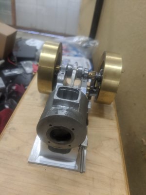
Bob Shores Eagle Hit/Miss Engine Build Thread

If your solder is not holding, the most common issues are not being clean, and the wrong temperature. Are you using the same flux that you use for electrical? Rosin flux will not work well on brass or stainless. Try it with some plumbers flux from the hardware store. For the temp most soldering irons used for electrical will not get enough heat into the parts to flow the solder. You may need to use a small butane or propane torch or a bigger iron. For parts the size of what you are doing I would be using a 100W to 250W soldering gun, Yest the kind that you should never use for electrical. If using a tourch, to hot will also cause the solder to not flow because it burns away the flux. Just like electrical, heat the parts and let the parts melt the solder, just enough heat to get the solder to melt.
 
I was having trouble getting it to flow in the gap. I was using flux-core wire, so I didn't bother to use flux. Guess I should have :)

The carb parts seem to be holding alright, and I'll keep it in mind if I need to fix either of those in the future. But if I can't get the bronze bearing to hold, I might give solder another chance.

Thanks!
 
Part 41: Starting the connecting rod!

So, I had a few hours today, so I decided to start on the last assembly: The connecting rod & bushings. I opted to make it out of aluminum, though I DID consider brass. While Brass would be cool, I wasn't sure it would be durable enough. I ended up buying both materials so I can do it over if it needs it :) I suspect this will take a few days of effort, but this is part 1!


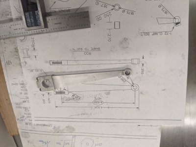
First, I used the horizontal bandsaw to cut the main bar and the bearing cap. I'd already measured the length I needed, since the plans (despite having dimensions) say to measure, and not trust the length dimensions.
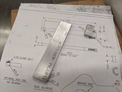
IMG_20200725_120623.jpg

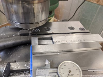
Next, I squared off both sides of the main connecting rod bar.
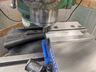
IMG_20200725_121034.jpg

THEN, I did the same with the cap.
IMG_20200725_121652.jpg

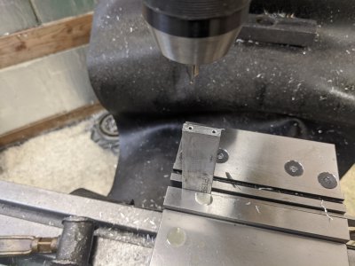
This setup was odd, but seemed to work. I spotted, drilled, and tapped the main bar for 4-40. I ended up screwing up the center on the X axis, but I made up for it later.
IMG_20200725_123348.jpg

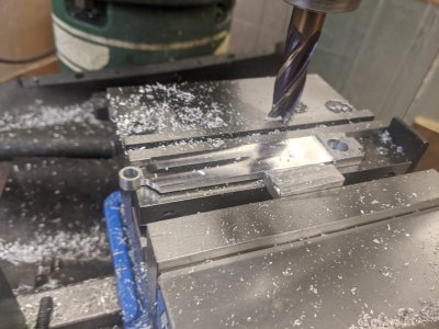
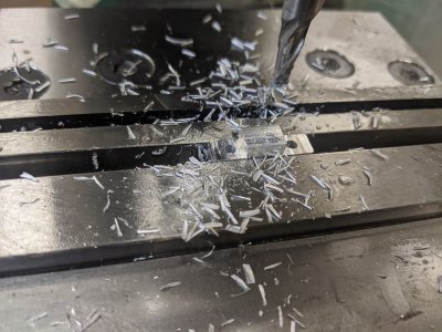
The cap required a bit of shaping, so I clearance drilled, then used a mill to clear out the spot for the heads of the bolts.
IMG_20200725_124709.jpg

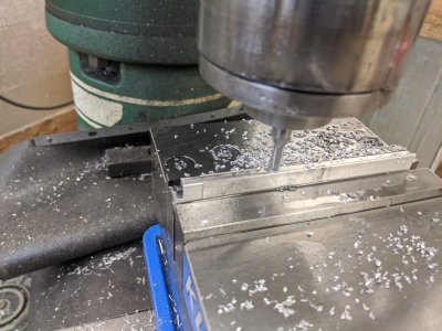
I connected the two (I actually shortened a pair of bolts on the grinder, since the ones I had weren't short enough!) and discovered I was off-center for the bolt holes about 10 thou on the connecting rod. I used the DRO, but I must have messed something up with edge finder. I took it down to the edge of the bolt heads on both sides, so it should just be roughly symmetrical now.
IMG_20200725_131041.jpg

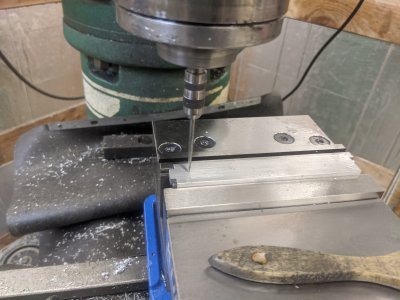
Next, I needed to drill the holes. The crankshaft side needs to be at the gap so I used a wiggler to find that point. I used the edge finder +DRO to find the center of the Y axis.
IMG_20200725_132328.jpg

I drilled the big hole (since I didn't have a matching reamer), but I reamed the piston side. I need to make a bushing anyway, so this was probably a waste of using the reamer. But *oh well!*.
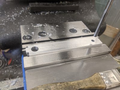
IMG_20200725_133309.jpg

Now that I have the 'functional' parts of the connecting rod complete, I need to do the shaping of it, first so it fits in the cylinder, and second so it looks nice! I popped my small rotary table next to the mill vise, and centered it with my coax indicator.
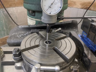
IMG_20200725_135906.jpg

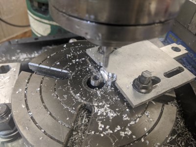
I used a .249 gauge pin in the spindle and used it to line up the rod. I ended up having to cut these clamp rods down since it was running into the spindle, which you'll see later (for you continuity fans: )).
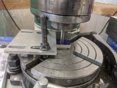
IMG_20200725_141651.jpg

I slowly fed in the X axis while cutting with a 1/4" end mill, rotating the rotary table near constantly. I ended up doing how close to the center of the rod by eye based on some lines I'd drawn, but I think it turned out pretty even.
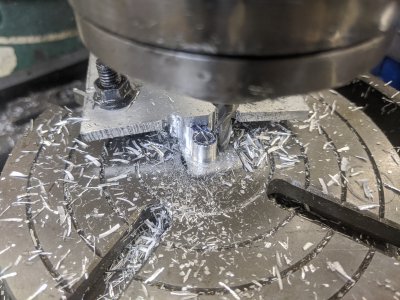
IMG_20200725_143918.jpg


AND this is it for the day! I'm likely going to need to do a little more work on the rotary table on both sides, but my clamp plate was too close to the part to do that side in that setup. I haven't decided on the rest of my order-of-ops yet, but I might set the 'thickness' of the main rod FIRST, which means going right back to the rotary table.
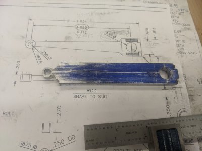
IMG_20200725_144126.jpg


So thats it! Hopefully I'll have more time to work on Monday.
 
Part 42: Finishing the connecting rod and bearings

Alright, more work today! I wanted to put a taper on the connecting rod in 2 directions, so I started back on the rotary table and cut out around each of the piston bosses.
IMG_20200727_132141.jpg

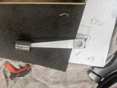
I calculated a little more than 1/2 degree angle got me about the layout I wanted, so i put in a sine bar with a 50 thou spacer and milled in the taper.

IMG_20200727_133709.jpg

I apparently missed pictures of doing the other direction, but tha tone I did by eye. i used a .249 stock in the 1 hole, then evened the top of the jaw of the vice with the bottom of the screw on each side. Then i milled it flat. Part done!
IMG_20200727_134909.jpg

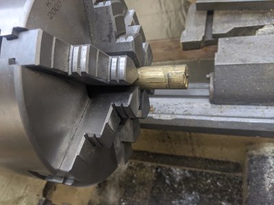
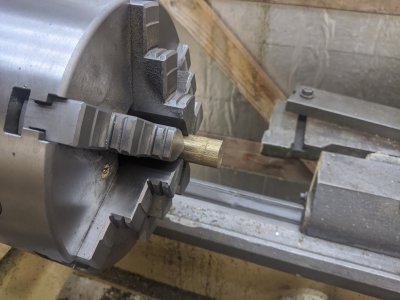
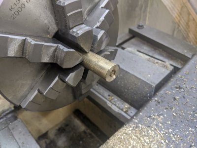
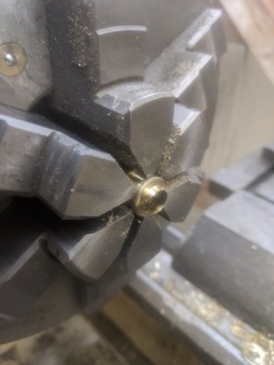
Then, I put my loctited 1/2 and 1/2 bronze in the lathe and started facing it off.
IMG_20200727_135007.jpg

Disaster... The glue failed almost immediately. Ther goes that plan!
IMG_20200727_135201.jpg

I flipped the rod around to do the small bushing for inside the piston. Easy enough!
IMG_20200727_135231.jpg

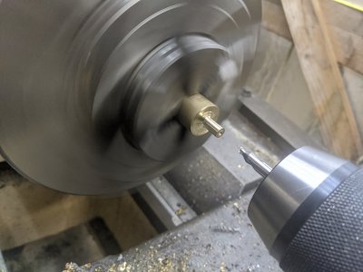
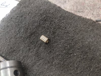
Turn down the outside to .250, drill/ream the inside for 1.875, then part and cut to length!
IMG_20200727_135901.jpg

Part done!
IMG_20200727_140804.jpg

And assembled in the piston.
IMG_20200727_141537.jpg

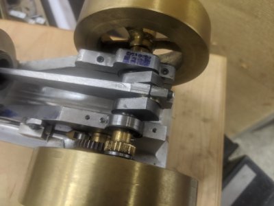
I decided to make the crankshaft part by just making 2 whole ones, then milling them in half. The first pair ended up cooling and shrinking enough that they no longer fit on the connecting rod. The second set ended up working. First, I drilled, tapped, and reamed .375 the crank shaft part.
IMG_20200727_142105.jpg

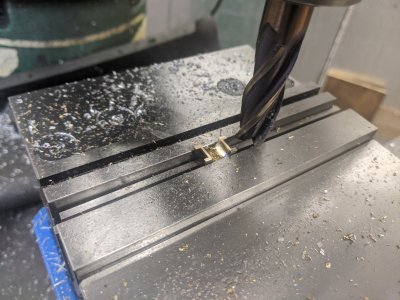
I profiled the outside and parted it off, I'm a bit out of order here (since the next piocture after this is from the 2nd try), but I used the mill (plus the bearing cap to align stuff, not pictured) to cut both in half.
IMG_20200727_150453.jpg


Before that though, I was just able to grab these in my 6 jaw and face to length.
IMG_20200727_154731.jpg

And installed! It was a LITTLE tight, but I used my drill to run it in a litttle and it runs pretty smooth!

IMG_20200727_160910.jpg

I DID lose my fly weights (and broke the springs) while running this with a drill, but it spun up easy enough! I used some way oil to work it in a little.
IMG_20200727_161330.jpg

I need a trip to Ace for more springs, then i need to spend some time assembling the electrical (likely next, so I can test the spark plug). Finally, I need to setup my fuel system time it, finish final assembly and checks, then see if it runs :) Hopefully not much longer to go!
 
Part 42: Fuel + Starting Electrical

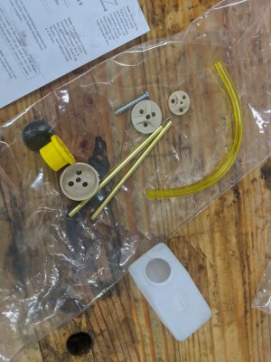
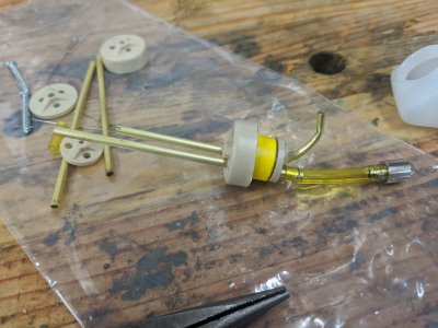
I started today with the fuel system! I started with a Sullivan RC plane tank + gasoline conversion kit. The kit went together pretty easily. It has a vent + a weighted feed that seems to assemble easily enough:
IMG_20200728_145057.jpg

First step is to put the brass rods through the rubber stopper, bend 1 side up into the little hollow (as the vent), and attach the weighted part to the feed side:

IMG_20200728_150123.jpg

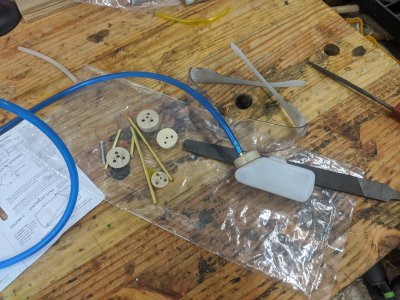
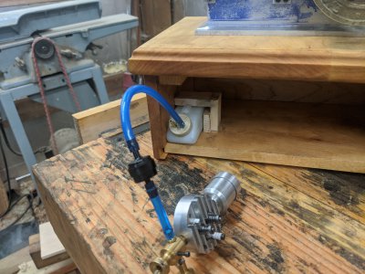
I shortened both brass hoses, then attached my fuel line (blue!) to the tank. You can see it fully assembled here.
IMG_20200728_151118.jpg

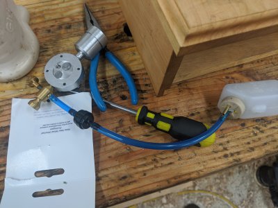
I have a fuel check valve inline as well (since hit-miss engines can starve themselves otherwise), and hooked it up to the carb. Fuel system done!

I ended up making a little wood bracket for inside the frame to keep the tank in place.
IMG_20200728_152023.jpg

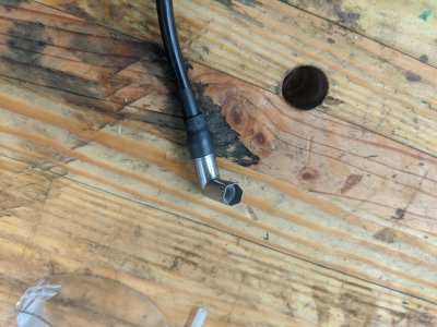
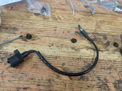
I am using a motorcycle ignition coil, so I had to break off the spark plug part and attach one for a 1/4" plug. I THINK this worked out alright, but we'll see when I go to fire this up :)
IMG_20200728_152647.jpg

IMG_20200728_152650.jpg

IMG_20200728_155814.jpg
 
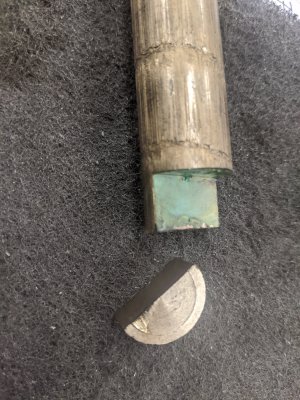
More GREAT work your doing !!!! If I'm understanding correctly you made the main bearing twice as long then milled it into a perfect halves ?
 
More GREAT work your doing !!!! If I'm understanding correctly you made the main bearing twice as long then milled it into a perfect halves ?
Thanks!

Yeah, thats what I did. Actually, I ended up making the main bearing _4_ times then milled into 1/2s, but I screwed up the first set :)
 
I spent the day yesterday and today trying to get the ignition to work, I used a motorcyle ignition (that took 2 spade connectors as input, and had a spark plug wire coming out of it), a small capacitor (according to the drawing), and a battery pack. I just couldn't get the coil to cause a spark! My contacts worked, the spark plug wire would spark (though very weakly) against the frame, but it just wouldn't spark the plug.

I gave up. Hemmingway kits suggest the https://minimagneto.co.uk/Products.php coil, and they have a kit that comes with a battery pack plus an ignition that will work with my contact points. Its a little expensive at $100, but the all-in-1 kit will hopefully 'just work'. Until then, I think I'm in a holding pattern. There isn't really anything else to do but wait :)

My fuel system is together, so I'm down to just electrical before I can give this a test run. I guess I'll be back in however long it atkes to get it :)
 
I have used this on another model with good results.

Have a look.
Ray
Hi, thanks! I saw a few of those around at about $50 (so half the other kit), but wasn't able to conclusively figure out if it would work with a non hall effect sensor. A couple of the forum post responses to people trying just said to use the HES :)

I probably should have just risked it, but I'm sick of this project :) I just want to fire it up and be done with it.
 
Back
Top