Bob Shores Eagle Hit/Miss Engine Build Thread

I don't think it's a good idea to bend a rocker arm as you have yours. You now would have the pivot point rocking and twisting which wastes motion and adds to wear. In a full size engine it would probably bend or break the rocker or the push rod or both. A better idea would be to align the tip of the push rod to the end of the straight rocker arm.

Just saying.
Eric
Unfortunately, I don't see how that is possible. The push rod height is fixed by the location of the camshaft gear, and the exhaust port/rocker pivot is fixed in place by the cylinder/piston location. I'm accurate to the plans within 2-3 thou across the whole thing, so I don't know how I could align this differently. I think this is just how the plans are setup?
 
Hmm... I saw a pair of videos on youtube of completed engines that didn't seem to have to bend the rocker (despite the plans saying you might have to).

I just don't see how you could get the cylinder to crankshaft relationship, crankshaft to camshaft relationship, bolt position (for the rocker holder), and exhaust port in the right place AND still keep both straight... I just don't see any layout that makes that happen, unless the pushrod was significantly closer to the cylinder...

Anyway, its a hobby motor that'll be run for a few dozen hours. If it becomes a problem I can remake the part in a material that won't bust, or re-engineer a way to have a bent one that doesn't cause the problem (like perhaps bending it on the exhaust port side?). Frankly, I'm going to skip out on hardening a couple of pieces that the plans recommend because I don't have the tooling to do so, but I figure this will run a handful of times and spend the rest of the time on a shelf anyway.

Thanks for the comment though, it really has me thinking about what happened differently on this engine.
 
That picture seems to still show the pushrod parallel to the ground. However, it DOES seem WAY lower than mine, which would mean that the cam gear is way lower too. I would understand if people were angling the push rod downward, but I don't see any pictures that do that.

FWIW, these plans have been really questionable. The amount of missing dimensions has been pretty annoying, and I can't help looking at other builds in a few cases like I've got different plans from everyone else. Additionally, all of the parts he recommends buying aren't even available anymore, which makes completing this engine an exercise in futility at a certain point. This whole kit is pretty infuriating...
 
You'll just have to solve the puzzle then. Apparently there are (were) corrected plans for this engine. I found a 2014 post referring to them on the floridaame site.

Eric
 
You'll just have to solve the puzzle then. Apparently there are (were) corrected plans for this engine. I found a 2014 post referring to them on the floridaame site.

Eric
Huh, I wish I knew if I had those, or what changed.
 
Could you contact the seller for your kit and see if they know?
 
Could you contact the seller for your kit and see if they know?
I guess I could try, but I would guess that they would be shipping the updated plans if they knew abou tit. That said, in retrospect, I'm not sure what it would change for me. According to the plans, I have a 9/11/01 revision.

However, all of the dimensions I know about are self-consistent, the only thing I can think of is that the base casting is too 'wide'. I based my measurements off the original casting (since there is NO dimensions for the base in the plans :(). If i was ~.400" closer, I would be right in line, or at least close enough that I could tilt the pushrod down to catch it. I've noticed that compared to the 'cylinder' casting, most of the other plans that I see have a much narrower base, so I suspect that is it. If it becomes a problem, i could probably take ~150 thou off to at least reduce the bend, but I think I've now commited to the pushrod location.
 
Day 29: Finishing the breaker

As you may have noticed, I'm slowing down recently :) Between being a little discouraged by a few issues and picking up the shaper (and making a 2 part vise!), I'm sorta working on 2 things at once. I AM doing my best though to make sure I finish at least 1-2 parts a day if at all possible.

I started with the isolator part, the other half of the breaker contact. I had a big chunk of plastic in my offcuts pile that I have no idea what it is from, but I milled this part off the end of it. The plans only ONE dimension (the width), so most of this is guessing/seat of my pants.
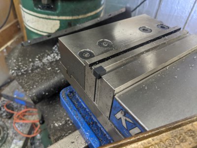
IMG_20200528_135755.jpg

I had to drill a mount point on one side, and tapped the other for the contact. The tapped hole ended up stripping when hand-threadng it in, so I ended up fine-tuning the contacts in a different way later.
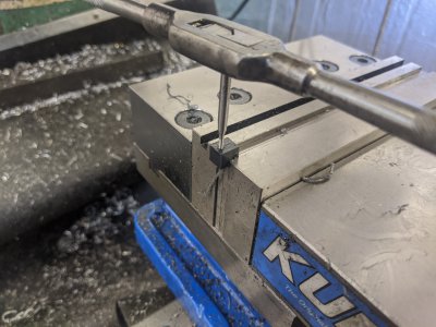
IMG_20200528_140814.jpg

At this point, I've drilled and tapped the 2-56 hole (to the right of the crankshaft) in the breaker plate. I drilled a #32 clearance hole for a 4-40 to mount this plate, at htis point I'm in the mill finding that hole so I can drill and tap to mount the breaker plate.
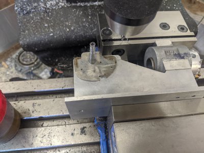
IMG_20200528_150208.jpg

I also took some spring stock to get the breaker 'return' working right. This .029 material seems to work great. The little tab on the bottom is supposed to catch it/ be sprung against, but I must have missed that it isn't when assembling (and put it under the bolt to keep it in place. I ALSO soldered the contacts in the two places they belong. On the isolator part, i ground the head of a bolt near clean off, then electrical-soldered (whatever the solder electrical people use is referred to these days, no longer Pb). its contact to it. On the brass breaker arm, I just soldered it directly to it.
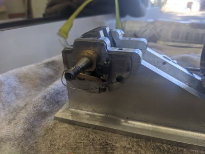
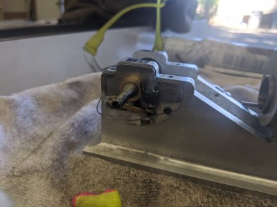
IMG_20200528_151625.jpgIMG_20200528_151635.jpg
 
I ended up getting distracted by surface grinder repair, so I didn't do much this weekend. I started on the flywheels by following the plan dimensions, and due to changing from a 20 degree angle, the flywheels were wide to start threading I unfortunately did a dumb, and decided that the flywheel should just be thinner instead, so I took 150 thou off the thickness. Fortunately, I only did 1 of the flywheels.

In reality, I should have just removed material from the 'outboard' side of the hub, but I didn't think about it. $40 for a replacement flywheel casting that should be here next weekend though, so I can fix that one.

Fortunately, on the other side I only faced 1 side, so I can trivially remove a bunch of the hub. Next time I have shop time I'll just make THAT one right and put it on the governor side so that I can be otherwise unblocked. I'll have to come back to the other flywheel when I get the new one in.
 
Back
Top