Bob Shores Eagle Hit/Miss Engine Build Thread

Day/Part 30: Flywheels and start of Governor

This one took a few days, but short ones. I made the flywheels! As my last post stated, I'll likely need to go back and remake the breaker-side one at one point, since I ended up cutting it too thin. The OD and inner features are also not alike, since I changed the design when I made the second one. However, It "works" well enough that I might just make doing this flywheel a future project if I decide to fix it up.

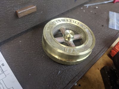
Here is one of the flywheels, I first set it up in the 4 jaw and turned the face and half the OD. The plans/guide say to hold it by the hub, but my chucks are too large for that. I tried to center based on the words, but that only turned out so/so. Both wheels were lopsided unfortunately, so I didn't get a chance to make them in a way that the 'USA' didn't get cut.

I also cut the hub. This is the side that faces the outside of the engine


IMG_20200529_152119.jpg
I flipped it around in the 4 jaw and discovered the problem I was going to have: How to indicate this in.
IMG_20200530_152444.jpg

This seemed to work out. machining the OD here ended up just about right.
IMG_20200531_111052.jpg

And a couple pictures of the 'done' wheels.IMG_20200530_164746.jpgIMG_20200531_114751.jpg

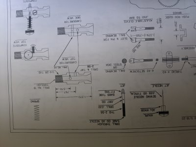
Next I made the governor collar. This attaches to the inside of the flywheel and holds the governor balls. The drawings on this are a little confusing, but hopefully I made this right anyway.

I turned the OD and made the ID on the lathe. I initially didn't realize that the hole went all the way through (temporary brain fart!) so I did it with a boring tool, rather than starting with a drill bit.
IMG_20200531_115712.jpg
Then to the mill! I cut away a bunch of the material. Those 'ears' will have pins in them to hold the governor arms. I also drilled the mounting holes in this setup using the DRO.
IMG_20200531_125011.jpg


Then, the pin holes. This setup was tough, but I did it with a parallel under the ears that I removed when drilling.
IMG_20200531_130012.jpg
I used a quare to setup this cut, which was to cut the clearance for the arms themselves. It actually lacked a couple dimensions, so I guessed. In retrospect, I probably should/could have cut this in the first operation, and just been OK with rounded IDs. I could have filed the arms round.
IMG_20200531_130714.jpg
And the part done!
IMG_20200531_131312.jpg
I set the flywheel up in the mill with the fly collar on it to find hte first hole. Since I used the bolt-circle tool on the DRO to cut them, I knew exactly how far they were apart. So this was as easy as finding the first hole, then just moving .887" on the Y axis.
IMG_20200531_131759.jpg

And tapping the holes 2-56.
IMG_20200531_132303.jpg
Here is how they go together!
IMG_20200531_132832.jpg
And a few pictures with ALL of the pieces I have so far attached. You can see the flywheel differences in these pictures. However, spinning the flywheels seems to work the way it should!
IMG_20200531_133400.jpgIMG_20200531_133406.jpgIMG_20200531_133412.jpg

So there we are! I'm a touch concerned that the thimble inside the collar doesn't have enough room to move enough to actuate, but I think I can remove some material from it if necessary. I could also potentially thin out the gears if need be. However, my dimensions are all to the plans (other than potentially the base, but that doesn't have dimensions on it, so *shrug*), so who knows?
 

Attachments

  • IMG_20200530_152452.jpg
    IMG_20200530_152452.jpg
    3.9 MB · Views: 13
I don't see 2 flywheels , I see one flywheel and the other wheel is for a flat belt that didn't get the crown machined in it . I fix a lot of my mistakes by making design changes lol
 
Part 31: Governor Arms
The governor arms move the thimble to enable/disable the engine(make it hit, or miss!). The plans say to drill a 2" bar of brass, then part off to thickness. I had a quick false start, then a bad one :)

First, I faced, then blued a 2" bar of brass. I drilled holes according to the pattern. The 3 holes on the right are to the plans, the left one was intended to be to help plan. The arms themselves are at a 5 degree angle to the holes, so I was intending to use it as alignment, I didn't think till after I drilled it that it is in the body of the arms. This will affect the project later.
IMG_20200605_135513.jpg
I then parted them off to length.
IMG_20200605_135759.jpg
However, I discovered a mistake in the layout plans. The small hole in the group of 3 is supposed to be a #52 (clearance for a .062 pin), BUT was actually in the plans as .052! When I tried to enlarge it on the mill, I messed up 1 of the pieces, so I decided to remake. The next time I made the alignment hole further outside the body. And here are the parted off parts. I blued them and marked off the arms at 5 degrees.
IMG_20200605_144811.jpg
I used the bandsaw to remove most of the material, then milled the flats on both sides (bandsawing the 2nd side after).
IMG_20200605_145627.jpg
Here they are after bandsawing, still needing to mill the other face.
IMG_20200605_150301.jpg

and here they are after milling the other face.
IMG_20200605_151229.jpg
I apparently missed the photos, but I then spent a bunch of time profiling with files. The next step was to make a 1/8" round section at the end. I used some 1/4" HSS blanks and a block of wood to square this up in the 4 jaw. Then, taking light cuts, I turned this down. This is still way too long, but I'll cut to length later.
IMG_20200605_161410.jpg

Then, I started cutting the 2nd one. And it freakin snapped off. All that work...


IMG_20200605_162342.jpg
Here they are together :(
IMG_20200605_162448.jpg

I ended up taking the better of the two from the first set and finished it about the same way. The turning of the round part went fine. However, note the extra hole, which annoyingly is still in the body. However, they look like they'll work.
IMG_20200605_172320.jpg

Next I need to make the weights! Only 2 sets of parts on this part of the governor, plus a single actuator arm.
 
So today was a redo day, though I didn't get any pictures. I remade the collar for the governor. The plans don't dimension the pivot hole locations, so I'd put them too close inboard. The result is the arms couldnt sit flat with a pin in them.

I made it the same way as before, except I used my 1/8" cutter wheel instead of an endmill. It allowed me to be more accurate, since I could put the flats on the vise jaws.

I also tried to build the flyballs, but kept being unhappy with how it was turning out. I think I'm going to change the design based on some pictures that I've seen. But, that is tomorrow's plan :)
 
Part 32: Flyweights/Flyballs.

The version in the plans say to use 1/2" brass rod, cut a slot in it and drill a pair of holes. I couldn't come up with a version of the slot that I liked, so I did some googling to find a different design for the fly weights. I've seen this design a few times, so I thought it would be nice! AND it allows 2 springs, which perhaps gives me more option for adjust-ability.


Fortunately, I had this 2 inch brass rod from the fly arms, so I turned it down, and center drilled it for the part. I am making a disk, which I'll then shape into the fly weights.

IMG_20200607_125053.jpg


A little side-disaster.... I was trying to measure and caught my poor dial indicator in the chuck jaws when it wasn't completely stopped. The top jaw is pretty mangled, the glass broke, and theres a nice little twist to the main bar. I'm glad it wasn't my fingers, but also sad to have lost these old girls :) I have a newer version (that came in a nice wood box!) of these as my backups, so they got drafted into service.

IMG_20200607_130720.jpg

Here's the disk. The center is drilled/bored to .700, .025 over the center fixture of the flywheel. I thought it was important for clearance, but after seeing it assembled, I don't think it matters.
IMG_20200607_131658.jpg

I flattened 2 of the sides a bit, then drilled and tapped for the spring holes, #4-40.

IMG_20200607_134504.jpg

These happened the next day, so I'd decide to flatten the other sides as well. Also, you'll note that I have the 1/8" holes to fit on the fly arms here. I blued it up, then cut it in half with the bandsaw. I considered using that .032 saw you can see in the lower left, but the bandsaw worked quicker :)

IMG_20200608_141725.jpg

And cut in half!

IMG_20200608_142013.jpg

I used the mill to flatten them to make sure they were the same. Despite them measuring the same thickness (and coming from the same ring!), I couldn't get them both to clamp together in the jaws, so I used some carbohydrate foam:

IMG_20200608_142518.jpg

And installed! The springs don't match (I need a trip to ace to pick up some better ones!), but this is how it works. They stick out a bit further than I'd like, so I may need to file the arms down a bit.
IMG_20200608_153508.jpg
 
Part 33: The stupid governor arm

So I've been working on/off on the project for a while, working on JUST the governor arm. I started with a 1/8" thick piece of construction mild steel from the Ace hardware. I cut out about a 3" section, then using a grinder and files, got it to shape. The first one I ended up making too short, the second I made the mistake of following the plans: I made the 'leg' that sticks up 60 thou, despite it going into a 118 thou slot in the governor. The 3rd one I made the entire body 'too thin', in an attempt to get rid of the scale. The 4th one I made a little over 100 thou for the arm, and only sandpapered as much of the scale off as possible.

Once I had the 1st 3 as guides, I was pretty good about setting up the size. However, I've spend the last about 2-3 weeks attempting to get the 'bend' right, it is very finnicky. I finally gave up today and moved the crankshaft a bit to to the side to get the governor to actually work right.

You can see in this picture how it is supposed to work, by stopping the union nut from going forward.


IMG_20200616_154317.jpg

Here's a picture of one of my earlier attempts I think.

IMG_20200616_154431.jpg

Here is the one I've got installed currently. The 'arm' on the right slides into the thimble that the governor weights move in/out on the shaft, and it engages the union nut. The total movement is probably about 10 thou, so you have to be pretty dead on to get this one to work unfortunately.

IMG_20200622_152309.jpg
IMG_20200622_152311.jpg

BUT, I think it is done.

I also tried to make the carb jet/needle, but drilling with a 32 thou drill bit (#67!) to use the needle has shown itself to be difficult. I suspect THAT will be my next set of frustrating parts to complete.
 
Alright, I had a bit of a false start with the carb jet. I discovered there is no way to drill a .032 or so hole in a piece of brass at .086 :) Its also incredibly difficult to turn something down to that size!

I DID happen to be in Ace yesterday, and discovered they had 3/32" x .014 wall brass tube! I thought that perhaps I could just use a piece of that, and use a bigger needle.

I brought it home and realized that the #2-56 thread has a minor diameter of about the same as the ID of the tube, so I obviously cannot use it ! However, I ALSO discovered that 1/16"x.014 wall brass tube is designed to be a 'telescoping fit' with the 3/32" tube, AND has an ID of .035! I can use a slightly bigger needle I think in order to just work with IT.

So I think the plan (1/16" tube is coming tomorrow) is going to be to make the jet out of 3 pieces:

1- I need the ID, which I get from the 1/16" tube.
2- I need the OD, which I get from a slight turn-down of the 3/32" tube, which I am going to use Loctite 609 to glue onto the 1/16" tube.
3- I need a 'hose' barb, which I'll turn to go around the 3/32" tube.

So the plan is to nest the tubes and glue them together. Then turn ~6 thou off the OD so it fits correctly in the carb. I then have to thread one end of the jet (with a die), and then 609 a hose barb on the other end.

I think I can raid my wife's needle drawer to find one of the right OD, and making the needle side of the carb should be slightly easier as a result.
 
Ugg... I'm about ready to punt this project into a river. After spending weeks on that stupid latch, I'm now on my 'weeks' into getting this foolish carb working too. I simply have no way to drill a .032/.035 hole 1" deep. I've broken all my drill bits even trying.

My thought about using loctite 603 to glue a 1/16 and a 3/32" tube together failed. I glued them, then filed the OD down to the OD I needed. THEN, I went to tap the end. However, instead of cutting the tap just tore the two pieces of brass apart. It pealed the outer part right off.

The annoying part is that this should be my last major hurdle. I need to make the piston/rod, which should not be terribly difficult, then build a base, assemble a fuel tank, put in a battery/do electrical. But this foolish jet/ jet needle doesn't seem doable. Unlike the weights, there doesn't seem to be any alternate designs that work here.

Anyway, thats why I've been making no progress on this. I've just hit a part that simply isn't makeable by me.
 
Can you post the drawings for the parts, maybe we can come up with some new ideas to try.
 
Attached! Sorry it is up side down. The "Jet" is the part I'm having a tough time with. I've already made the carburetor body. According to the instructions, the ratio of Carb ID + jet OD is the important one, so the .087 and .166 are not really changable. I could increase these sizes, but I'm limited by the 1/4-28 thread at the end of the body.

SO, I need an ~1" long piece with a .087 OD and a .032 or .035 ID. I could possibly use a slightly larger needle, but I risk getting pretty darn close to the inner thread dimensions of the 2-56. I've broken all my #67 drill bits (it was a lot...and really good ones!) trying to peck-drill this almost 1" long.
 

Attachments

  • IMG_20200629_154344.jpg
    IMG_20200629_154344.jpg
    1.3 MB · Views: 16
Back
Top