Bob Shores Eagle Hit/Miss Engine Build Thread

Day 22: Starting the Carb

I have been looking through the plans, and am a bit stuck on what I can make based on waiting on materials/tools, so I decided to make the body of the carburator, the only part I can actually make of the assembly! The plans are VERY quiet about the design of the carb, and seem to expect I know more about them than I do. The dimensions are missing on a lot of it, so I end up having to guess on this a bit. This part is pretty clear, but the other two components are a bit confusing. If I cannot figure out how to do it I might post a picture of the plans and make you guys help :)

I opted for brass, sadly I only had 1 1/2" brass. I first turned it down to about 1/2":
IMG_20200517_105230.jpg

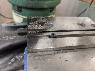
Then I did a rough shaping. In general, this is just preference.
IMG_20200517_110734.jpg

The instructions to the plans claim that the drill-through is only 1 of two dimensions that actually matter on the carb (the other being the OD of one of the other parts). I drilled through, and then used a larger drill bit to create the taper (which is apparently unnecessary as well).
IMG_20200517_111415.jpg

Then I parted it off, turned it around, then used a die to cut the threads:
IMG_20200517_111856.jpg

Next I need to drill through for the jet/needle parts. That went very easy.
IMG_20200517_112922.jpg

Then I rotated it 90 degrees to drill through 1/2 way for what I believe is a throttle screw (for lack of a better term?). The throttle screw is #2-56 in the plans, though again not sure how necessary that size is. Everything went well until it went to retracted the tap and a few turns it broke. It broke near the bottom of the hole! I was actually able to use a pair of pin tools to spin it out (like a tap extractor!) and managed to save this :) IMG_20200517_114658.jpg

And installed! The throttle screw right now is pointing the other way, so I'm sure thats wrong.
IMG_20200517_115043.jpg
 
Here are the plans for the carb:

First, I've got no clue what that 2-56 bolt does in the side of the body.

Second, It looks like the jet-needle (with the knurled knob) is supposed to be the adjustment for the mixture, but it doesn't show it threaded to go on the Jet itself? Should I thread the bottom of the knob for 2-56 for the Jet? I would think it would have to be, right?

Then, it looks like there is a nut of some sort holding the jet in place, but I don't see why the spring would be needed. What would that be for?

The Jet OD is the only other thing the plans say matter, so do you think I'd be OK drilling the oriface to .040? It calls for .030, but thats a tiny drill bit! A #69!
IMG_20200517_125723.jpgIMG_20200517_125731.jpg
 
Day 23: A little work on the breaker
Another part of the assembly where the plans fall a little short is the breaker. First, he specs tungsten rivets as contacts that apparently don't get made anymore. I found some solder-on tungsten parts i think I'll use.

The assembly is all bolted to a single piece of sheet metal which houses a bunch of holes for mounting everything. I figured I'd start by cutting the main hole there, then working on a few little pieces (I didn't have much time this evening).

Here is the plate drilled. Eventually, I'll end up having to shape this quite a bit to match the body, but that comes later.
IMG_20200518_171848.jpg

I also need a small bronze bushing, so this was my first time cutting bearing bronze. It went quickly and easily!
IMG_20200518_172430.jpg

And here it is done. Eventually this is going to be a part of the breaker-arm.
IMG_20200518_173650.jpg

Next, I decided to make the breaker-cam-thing. I forget what the instructions call it, but it allows the breaker arm to complete the circuit. It is .625 around, .250 thick, and a .376 hole in the middle. Another easy one:

IMG_20200518_173917.jpg

IMG_20200518_175002.jpg

I flipped it around, and faced the other side! I ended up reaming to .376, since my first attempt at this was too tight.IMG_20200518_180716.jpg

Next in the mill, I cut the cam itself then a 2-56 tapped hole for the set screw. Some may remember I broke my tap! Fortunately the brass was soft enough to be easily tapped despite the tap not having a taper in! I've got another one coming since I have some more difficult metals to tap later.
IMG_20200518_183135.jpg

And mocked up how it will fit someday. Hopefully someday soon!

IMG_20200518_183331.jpg


I've got a fairly sizable list of things left to do, though quite a few tasks are either blocked by not wanting to do the part just yet (since it doesn't attach to something else), or needing parts/materials to come in. I'm sort of just trying to make sure I finish a part or two every time I have some time in the shop, otherwise I'll never get this done!
 
Day 24: Some Breaker work

Still waiting on some other parts, so I did some work on the breaker. I can't go too much further as I believe I need to wait for the contacts to arrive, but I got a bunch of work done!

First, I needed a shoulder bolt to attach the moving part of the breaker. The plans specify a part number for something not available. It was easy enough to turn and use a die to thread.
IMG_20200519_140736.jpg

I had this cutting tool and cut the slot. I'm not a huge fan of this one and might remake it someday (the head is pretty bad because I didn't want to get too close to the chuck!). BUT, it still works for now :)

IMG_20200519_141920.jpg


The next part is interesting, it is the breaker arm itself. The plans call for it to come out of a piece of sheet brass. Here is some .015 sheet brass that I folded over a paraellel to get the shape.
IMG_20200519_143811.jpg

IMG_20200519_143818.jpg

It ended up getting mushed around a touch as the part went together, but it seems like it'll still be functional. In order to drill the holes, I took a scrap piece of aluminum and cut it down to 1/8". Then wrapped it around and used it this as a way to clamp it in the vise:

IMG_20200519_144826.jpg

These two holes (in the top) were pretty easy. One is for the contact terminal, the other is for the part that rides the cam. I don't know how the contact terminal attachment is going to work (since it is soldered in), but we'll see :)

IMG_20200519_145926.jpg

I also had to turn the part that touches the cam (you'll see it better in future pictures, my lens got oily at one point!). I turned it out of HPDE I had around. Missing from this image is the hole for the piece of spring-wire that goes through this, but I ended up drilling that with everything assembled.

IMG_20200519_153943.jpg


And here is the parts assembled! I still need to do some work to make the other side of the contact work, but I have some material for the 'isolator body' that I just need to make into the correct part.

IMG_20200519_155427.jpg

Finally, I did some grinding on the breaker plate! I got the shape just about to where I'm happy-enough. I also turned up the little tab on the lower right (2nd picture) which the other side of the spring rests against, which you'll see in future assemblies :)

IMG_20200519_170611.jpgIMG_20200519_170912.jpg

On the breaker, I need to create the mounting bolt and add the isolator assembly. I'll likely leave the wiring to another time. But its close!

I think I have some parts to start on the pushrod assembly coming soon, so those might end up coming up before this is finished as well.
 
Day 25; Starting on the pushrod assembly

I'm a little all-over-the-place lately, I've been waiting on materials and getting a little discouraged by failures along the way, so as a result my progress has been a little disjointed. I'm now keeping a list of parts-to-complete, so hopefully I'll be better about it in the future! Yesterday I spent the day cleaning up my new shaper, so I made no progress.

I decided to put the breaker assembly aside for a little while, as I'm awaiting the contact tungsten pieces. Instead, I first started with the rocker arm. My first three attempts at this tried turning them out of one piece on the lathe, then doing the mill work. However, I was completely unable to do the mill work without bending the threaded rod section (even before threading!). SO, I chose to instead make just the top and use threaded rod. This is the rocker arm in progress. I used the collet block stood straight up to cut the square (it calls for 1/4" square stock, I used 3/8 round). I also cut the center cutout with it. Then I turned it on the side and drilled the mounting hole, and tapped it.

IMG_20200521_150420.jpg


On the lathe, I rounded over the back side with a lathe tool and parted it off. However, first I drilled/tapped down the center for the threaded rod. The threaded rod I bought came in yesterday, so I was able to cut a piece for it and red loctite it in!
IMG_20200521_152249.jpg

And the part installed on the head with a washer and nut. I might find myself wanting to shorten this part, as this is as low as it goes, but we'll see when I get the rocker arm completed.

IMG_20200521_152425.jpg


Next, the first part of the pushrod toward the head is just piece of 1/8" steel with threads on one side. My chuck couldn't hold something this small, so I used the bench grinder to turn down the 1/8" to .112 so that I could thread it 4-40. Easy peasy! 2nd part for the day done!

IMG_20200521_153635.jpg

I also got the threaded collar in today that goes in this, but I didn't take a picture.
IMG_20200521_153947.jpg

Finally, the other end of the pushrod assembly, the part that holds the bearing that rides on the cam. I did this the same way as the rocker arm. The plans themselves call for this to be a much longer part before the threads, but it didn't seem worth trying to turn something that small and still have to mill it. I pressed in a part of that same 1/8" steel rod through the bearing, and can consider this done!

IMG_20200521_170545.jpg

The pushrod assembly requires a 'union nut' (a 1/4" square piece threaded down the middle) and a two mounting brackets. The union nut is supposed to be 3/4" long and I have no idea how to thread down the center of that! The longest 4-40 tap I have is .400 long. It also wants some sort of hardened steel. Instead, I bought a stainless coupling nut 1" long. It is a hex, so I'll have to shorten it and mill it to a square, but that seems WAY easier. I'll have it in my hands tomorrow from Mcmaster!

I think the brackets themselves are dependent on the shape/size of the union nut, so I'm holding off making them a bit more. I SHOULD be able to make the rocker arm next, but I was having a little 'analysis paralysis' when trying to figure out what to make it out of!

Also of interest, I got my fuel tank in today! I ended up buying a 1 oz RC fuel tank, which seems like a better idea than trying to make one. I have to make a wood base for the motor anyway, so I can hide the tank in there.
 
Day 26: This part made me tired!
I worked on the exhaust of course :)

But first, I wanted to do the rocker arm. I was at Ace and they had 8 ft of 1/8" steel for $11, so despite only needing 2 inches of it, i went for it. I ended up using the angle grinder to cut a piece off (then screwed it up, and used the OTHER half!).

IMG_20200522_131358.jpg

I shaped it in my mill (milled both long sides to thickness, then the ends to length), then drilled the pivot hole:

IMG_20200522_135216.jpg

A little shaping on the belt grinder, then I put it in place! it seems to work!
IMG_20200522_140050.jpg

Next, the exhaust. I ended up messing this up a few times. First, I think I got a defective round-die in the mail, it wouldn't start until the OD was like .280! I went and got a hex die at Ace today so that I could make it right. I only messed up once here. I had turned the OD of the threaded portion FIRST, then my drill bit in the center wondered a bit and took it all out!

The plans say to make this a little larger, but this is what I went with. About 1" OD, and a little less than an inch long. I turned the back side down and did some cleanup for looks, drilled through and threaded the end with the die:

IMG_20200522_141208.jpg

IMG_20200522_141214.jpg

Then I parted off with the bandsaw and did a test fit! This is good, because the first one I did I forgot that I needed to leave room for the cylinder itself (I counted the threaded section as stickout).

IMG_20200522_142836.jpg

Here's where I decided to get lazy AND creative at the same time. I opted to thread on the top. I ?think? the plans (which are horrifyingly under specified for this part as it is a 'do what you want' type part) have you solder the cap on. I threaded. Something like .955-28.IMG_20200522_144540.jpg


I used a boring bar and some drills to hollow out the inside. The threads have a handful of burrs on them, but turned out acceptably.
IMG_20200522_145737.jpg

For the cap, I just hollowed out the back, drilled through (it made hollowing out the center easier!), and threaded the inside. I did NO math here. I started by turning the inside to what looked like almost the right size, then started cutting threads. However, it turns out I was re-cutting threads with the bottom of my tool! SO, I ground the tip 'pointy-er' (basically, more relief angle under the tool) and started cutting again. 2 or 3 passes, and it nearly fit! i was as shocked as anyone! I used the file to clean the threads a little, did a spring pass, and it fit reasonably well. I called it a win.
IMG_20200522_155647.jpg

I put them on the mill and used the bolt-circle tool to cut a hole pattern. It ended up slimppinga little, so they are a touch uneven (look at that bottom middle hole!), but good enough for an exhaust.
IMG_20200522_160907.jpg

I spent $8 on this bag of fluff online. I needed about 1/500th of it, but I used it to stuff my exhaust 'loosely'. I made sure I could still blow air through the exhaust to make sure I didn't make it too tight.
IMG_20200522_161047.jpg

AND installed! You can also see the rocker arm here!

IMG_20200522_161212.jpg

I'm not sure what I'll do tomorrow, I got the contacts in for the breaker and I got the union nut for the push rod, so both of those are unblocked as far as I can tell. It would be nice to get a whole assembly DONE, so I might try to do 1 or both this weekend.

I still have quite a bit of work to do, I have to finish the carb, the breaker, the pushrod assembly, turn the flywheels, make the governor assembly, do the piston+rings+connecting rod, AND do base, which includes the electrical work and fuel tank. I figure I'm just about past the 1/2 way mark, but it has been a long project already.
 
Day 27: The rest of the pushrod assembly

SO, I had opted to not build the union nut since I couldn't tap .750 in 4-40. I started with a hex coupling nut from mcmaster 1" long, milled down the sides, and milled it down to .750. Easy peasy :)

IMG_20200525_105010.jpg

I also opted to just buy a collar. Unfortunately, they were significantly larger than the room I had. I have .250, and they were close to .400 thou! So, I milled a flat across from the screw. This will also help keep the push rod straight hopefully.

IMG_20200525_111347.jpg


And the assembly complete! I ended up having to mill the brass part thinner because I dum-dum'ed and didn't think about how it needed to get in a .250 gap! I'll also someday need to thin out that nut as well (or make my own!), since it is greater than .250 on the diagonals. I might just turn it into a 12 side with the belt sander eventually.
IMG_20200525_111611.jpg

The plans call to make these out of brass, but mine are aluminum. Its what I had around. After all the work on this one, I found out that it was too close to the top of the engine base for the top bolt to be worth anything, so you'll see it in 1/2 later. I made this one, and one with a circular hole to hold the push rod.

IMG_20200525_123909.jpg


I spent A LOT of time doing the layout here, then drilled/tapped in the mill. The plans call for 2-56, but I didn't want to deal with that again. SO I went with 4-40. It makes the brackets a little larger, but since I took one of the ears off one, this seemed like a good idea :)
IMG_20200525_133630.jpg


AND in place! I also made another spring (that was an adventure!) to mount it. I spent quite a while doing the layout here to make sure it is right, however I still wonder if I'm a little low. When the cam comes 'downward' it binds a little, though is perfect in the other direction. That might just decide the ignition direction of the engine.

You'll notice the rocker-arm is missing here. The plans call to bend it to line it up. However, as soon as I tapped on it in the vice, it snapped in 1/2 at the screw hole. I guess I need to make it again! Next time I'll probably use the torch to heat it up first though!

IMG_20200525_145100.jpg

I was really hoping to have this whole assembly done this weekend, but I opted to spend a 2 days this weekend (a 4 day weekend!) cleaning up my (new to me!) shaper's table and making most of a vise for it so that I could see it cutting.

Hopefully during the week I can re-make the rocker arm and finish up the breaker assembly. That'll allow me (by my own rules) to finally machine the flywheels!

After that, I still have the whole governor assembly, the piston /connecting rod, electrical, base, and fuel tank, plus finishing up the carb! So still a while to go...
 

Attachments

  • IMG_20200525_111154.jpg
    IMG_20200525_111154.jpg
    4.1 MB · Views: 10
Day 28: Remaking parts:

So two things: 1, the rocker arm itself I broke trying to bend it, so I had to remake it. This time I used a thicker material (my 1st attempt at remaking it drilled too close to the edge and popped through, since it is a .116 hole in .125 stock!) in the dimension that goes perpendicular to the bolt. It make a few things easier. Bending it was as simple as putting it in the vise and hitting it with a mallet.

Secondly, I noticed the pushrod was binding/flexing instead of moving in/out. I presumed it was my modification to the near-bracket that wasn't sufficiently supporting it. SO, I made a 4 bolt version that is quite a bit tighter. Only 3 of the bolt holes ended up being useful, but it stops the problem I was having. I didn't take many pictures as I went, but here it is all done:

IMG_20200527_155717.jpg

IMG_20200527_155714.jpg
 
I don't think it's a good idea to bend a rocker arm as you have yours. You now would have the pivot point rocking and twisting which wastes motion and adds to wear. In a full size engine it would probably bend or break the rocker or the push rod or both. A better idea would be to align the tip of the push rod to the end of the straight rocker arm.

Just saying.
Eric
 
Back
Top