-
Welcome back Guest! Did you know you can mentor other members here at H-M? If not, please check out our Relaunch of Hobby Machinist Mentoring Program!
You are using an out of date browser. It may not display this or other websites correctly.
You should upgrade or use an alternative browser.
You should upgrade or use an alternative browser.
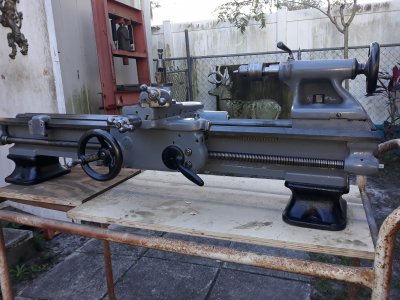
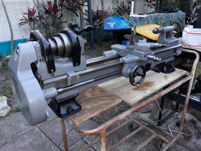
South Bend 9 C Lathe Restoration
- Thread starter LX Kid
- Start date
- Joined
- May 26, 2015
- Messages
- 776
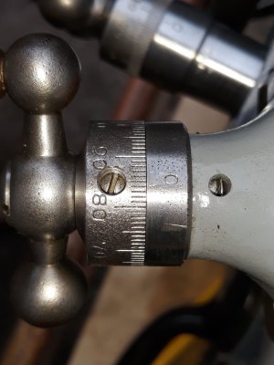
Good point. I'll clean the paint off. ThanksAlso, that area where the 0 index mark is stamped should not be painted. It is a precision surface.
- Joined
- May 27, 2016
- Messages
- 3,477
The usual single phase induction motor uses a special sort of AC capacitor to make the artificial "live" for the other winding. Reversal is by swapping which gets the real live with which gets the supply via capacitor.
Are you fully OK with the motor type, how to connect for reverse, full torque, inbuilt centrifugal spring switches, earth connection safety via your house RCD (Residual Current Device), etc?
I only say this because it has to be right, especially if it was previously powered by generator, and grounded one end of the supply. You do not expect that the ground is connected to anything other than the metal frame, and that the power wires do not share that ground.
You want that in the case of loose swarf or chips contamination into the motor, or even stray wetness, or any kind of earth leakage or burnup, the house RCD will detect the leak, trip out - and save your life!
- Joined
- May 26, 2015
- Messages
- 776
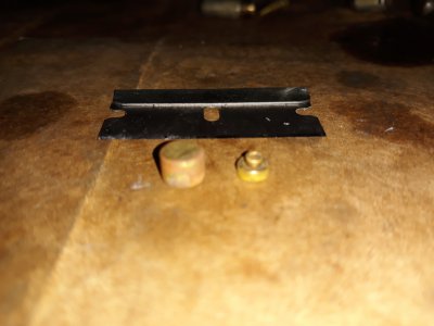
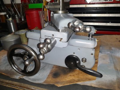
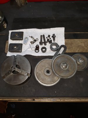
Got a little problem. I've got everything ready for headstock re-assembly "but" in the bottom of my cleaning pan I found two little tiny brass pieces that I don't know where they fell out of. Does anyone know where they go????
Attachments
- Joined
- Mar 15, 2019
- Messages
- 708
One on left looks like shoe to back gear adjustment screw.
- Joined
- May 26, 2015
- Messages
- 776
Uhhh, where exactly would the gear adjustment be located?? I just layed the headstock on the lays for the picture. Still some more gears and parts to install.One on left looks like shoe to back gear adjustment screw.
Attachments
- Joined
- Mar 15, 2019
- Messages
- 708
At the little gear end of back gear shaft. It goes under the screw that goes through part of headstock the back gear shaft rides in.Uhhh, where exactly would the gear adjustment be located?? I just layed the headstock on the lays for the picture.
- Joined
- May 26, 2015
- Messages
- 776
I think I know where you mean. There is a special tapered set screw in there now that engages into the handle so it doesn't throw too far. I'll take a pic of it tomorrow. How about that other tiny brass piece? Could it be it fits under the set screw of the compound degree retaining set screw?At the little gear end of back gear shaft. It goes under the screw that goes through part of headstock the back gear shaft rides in.
Attachments
- Joined
- May 26, 2015
- Messages
- 776
The usual single phase induction motor uses a special sort of AC capacitor to make the artificial "live" for the other winding. Reversal is by swapping which gets the real live with which gets the supply via capacitor.
Are you fully OK with the motor type, how to connect for reverse, full torque, inbuilt centrifugal spring switches, earth connection safety via your house RCD (Residual Current Device), etc?
I only say this because it has to be right, especially if it was previously powered by generator, and grounded one end of the supply. You do not expect that the ground is connected to anything other than the metal frame, and that the power wires do not share that ground.
You want that in the case of loose swarf or chips contamination into the motor, or even stray wetness, or any kind of earth leakage or burnup, the house RCD will detect the leak, trip out - and save your life!
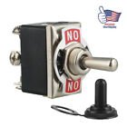
Pretty sure Blk & Red is one direction and Blk and Yel the other direction. I'm going to gut the switch assembly can and put a double pole double throw toggle switch in it's place.