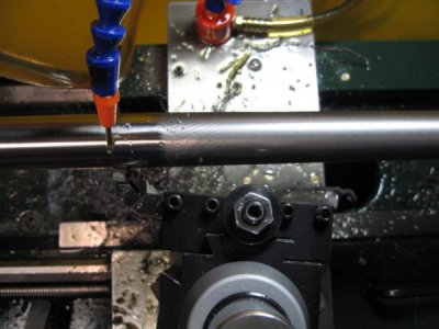
I've been thinking about this some more.
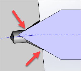
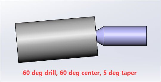
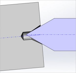
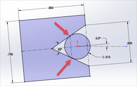
Here's some sketches showing a conventional 60-deg center drilled part. I just used #4 center drill geometry but they are generically similar through size progression. The turned part itself is angled at arbitrary 5-degrees in top view, just to show exaggeration in offset tailstock taper turning mode. And then showing 2 styles of tailstock support centers - a typical 69-deg cone and a ball ended profile. The dimensions aren't important, more just a visual thing. Here are my eyeballing observations, see if you agree.
It seems to me that the 60-deg support can only have one point of contact. Either on the lip end of the part or possibly the inside corner where the smaller pre-drill transition. And I think 'point' is the right term (viewed in mid plane horizontal section view). It cant be a line if there is any offset. That can only occur when axis are coincident. There may be one unique setting where the center is supported by both corners mentioned, but that doesn't help us much & probably isn't desirable.
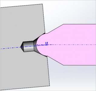
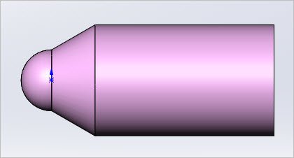
The ball end support superimposed inside the 60-deg center drill cone has a resultant 'circle' as a tangential ring constantly in contact. I drew it up in 2D just to confirm the geometry satisfies this & it does. The tangent contact occurs in slightly different positions (red arrows). I was having trouble 'mating' the parts in 3D but that was probably just me. Actually the ball would work for any angle like 45-deg chamfer, just showing 60-deg for similar comparison.
So now add tool cutting pressure to one side of the parts arrangement & a bit of wear on whatever makes contact. Seems to me the ball has to be better. Its spreading that side imposed load on at least half the tangent arc. The 60 cone within a cone is concentrating all that pressure on one teeny point area. What do you think? Am I barking up the wrong tree?
Some other points to ponder
- re the special curved profiled center drills. I don't know what kind of curve they have so cant really draw them up. But I could visualize where they might have similar connected ?circular? contact similar to the ball. At least they would prevent potential interference with the pilot drill. But this presumes you can actually drill your part. In the case of gun barrel this might not me an option, or not without a secondary lopping off operation.
- a 60-deg live center in a 60 deg hole. What's happening here? Its kind of teh same point contact thing but maybe better? The part would drive the center even though not on the same axis, kind of like bevel gears in principle? If so, that might be an improvement over 60-deg dead center. (But more work to integrate a live center bearing assembly into a boring head used for offset.
- and thus far we have been talking about the tailstock end. But seems to me the exact same geometry issue is happening at the headstock side if its got a typical dead center & drive dog arrangement. The relative part-to-dead center doesn't care that the displacement is higher at the TS end, its the same angular difference the 2 axis on either end, no?


