-
Welcome back Guest! Did you know you can mentor other members here at H-M? If not, please check out our Relaunch of Hobby Machinist Mentoring Program!
You are using an out of date browser. It may not display this or other websites correctly.
You should upgrade or use an alternative browser.
You should upgrade or use an alternative browser.
Tool and cutter grinder build
- Thread starter Mark_f
- Start date
Well, The spindle is completed and on the machine. Now I need to make the motor pulley and get a belt to test run it.
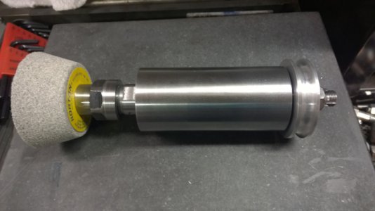 This is the spindle all ready to go. I cut some flats on the spindle to accommodate a 7/8" wrench. I made the pulley from aluminum and used my lathe to broach the 1/8" key way in it. The pulley is 2.4" O.D. I may make the motor pulley 3" to get about 4100 rpm on the spindle.
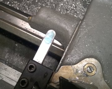 This is a 3/8" HSS tool bit ground with a 3/16" radius to plunge cut the pulley groove for a 3/8" round belt. It worked really well as long as the speed is right and the cut is light.
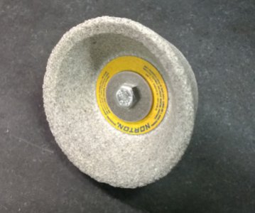
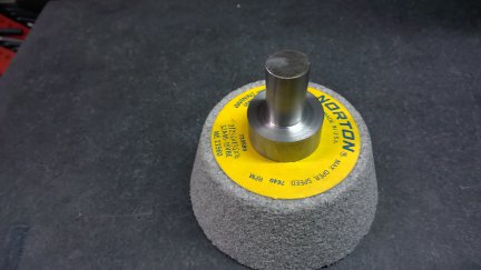 I u8sed a piece of 1" round stock to turn an arbor for the stone I have. This is a coarse 3" stone good for roughing. The arbor has a 1/2" shaft and a step to fit the stone ( .500" O.D. X .375" long) and a 14-20 tapped hole for the bolt. Each stone will have its own arbor and they can be changed out easily.
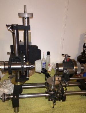 The spindle is on the grinder and I put about 1 1/2 ounces of turbine oil in it. then remembered, I should drill a tiny vent hole in the oil plug before running it. It is all ready to go as soon as the motor pulley is done.
I discovered a problem with the spindle. It is purely cosmetic and won't really affect its operation, but I may have to make another spindle shaft. The 25 mm die used to cut the threads on the spindle shaft seems to have made the threads a little looser than I would like them. They work, but are kind of loose. I first put everything together and checked it for being straight and running true. It was. I spun it in the lathe and everything was straight as an arrow. I took the nut off and put it back on and it was crooked , by quite a lot in my opinion. The shaft is true, the collet is true , but the nut is crooked. I put it on and off several times and it keeps going crooked. The collet registers in the taper, so it stays true. So, my brilliant idea to fix it is to put it on and turn the ends and O.D. in place and it would look straight. And it did. Everything now looked good until I took the nut off and put it back on and it is crooked again. No matter how many times I take it off and put it on it is crooked. Now, this won't affect anything but looks because the nut has a wobble to it when the spindle turns. At 4000 rpm, it won't be noticeable and stopped it looks ok. It will also be hidden by the stone cover or shield or what ever it is called, but it bothers me. It will have to do for a while and maybe later when I get the gears made to cut metric threads on my lathe , I will fix it by single pointing the threads. I spent hours fussing with this nut.
 This is the spindle all ready to go. I cut some flats on the spindle to accommodate a 7/8" wrench. I made the pulley from aluminum and used my lathe to broach the 1/8" key way in it. The pulley is 2.4" O.D. I may make the motor pulley 3" to get about 4100 rpm on the spindle.
  This is a 3/8" HSS tool bit ground with a 3/16" radius to plunge cut the pulley groove for a 3/8" round belt. It worked really well as long as the speed is right and the cut is light.
 I u8sed a piece of 1" round stock to turn an arbor for the stone I have. This is a coarse 3" stone good for roughing. The arbor has a 1/2" shaft and a step to fit the stone ( .500" O.D. X .375" long) and a 14-20 tapped hole for the bolt. Each stone will have its own arbor and they can be changed out easily.
 The spindle is on the grinder and I put about 1 1/2 ounces of turbine oil in it. then remembered, I should drill a tiny vent hole in the oil plug before running it. It is all ready to go as soon as the motor pulley is done.
I discovered a problem with the spindle. It is purely cosmetic and won't really affect its operation, but I may have to make another spindle shaft. The 25 mm die used to cut the threads on the spindle shaft seems to have made the threads a little looser than I would like them. They work, but are kind of loose. I first put everything together and checked it for being straight and running true. It was. I spun it in the lathe and everything was straight as an arrow. I took the nut off and put it back on and it was crooked , by quite a lot in my opinion. The shaft is true, the collet is true , but the nut is crooked. I put it on and off several times and it keeps going crooked. The collet registers in the taper, so it stays true. So, my brilliant idea to fix it is to put it on and turn the ends and O.D. in place and it would look straight. And it did. Everything now looked good until I took the nut off and put it back on and it is crooked again. No matter how many times I take it off and put it on it is crooked. Now, this won't affect anything but looks because the nut has a wobble to it when the spindle turns. At 4000 rpm, it won't be noticeable and stopped it looks ok. It will also be hidden by the stone cover or shield or what ever it is called, but it bothers me. It will have to do for a while and maybe later when I get the gears made to cut metric threads on my lathe , I will fix it by single pointing the threads. I spent hours fussing with this nut.
B
Bill Gruby
Forum Guest
Register Today
You have done well Mark. Very professional job.
"Billy G"
"Billy G"
You have done well Mark. Very professional job.
"Billy G"
Thank you.
It doesn't feel like it is going quite as it should sometimes. The little details take as much effort as the main build it seems. Some of the little problems bother a perfectionist like me and that can be hard to work through.
I used my new die filer to finish up the key way in my pulley. It came in handy already.
Last edited by a moderator:
Wow, that's a very impressive job Mark. Thanks for the great documentation!
Sent from my iPhone using Tapatalk
Thank you
- Joined
- Mar 25, 2013
- Messages
- 5,129
Extremely impressive Mark. Sorry to hear about the thread issue. Perhaps your next project should be those metric change gears?! Still your machine looks very professional. Oh and yes, very entertaining. Can't wait to see some tool grinding.
May I ask about the spindle? I have not yet made one with ball bearings. Do you have 2 sets of matched bearings (one set at each end) or do you just have two bearings total. If the latter I don't understand how you get the preload right. I thought the bearing faces had to be in contact for that to work?
R
Extremely impressive Mark. Sorry to hear about the thread issue. Perhaps your next project should be those metric change gears?! Still your machine looks very professional. Oh and yes, very entertaining. Can't wait to see some tool grinding.
May I ask about the spindle? I have not yet made one with ball bearings. Do you have 2 sets of matched bearings (one set at each end) or do you just have two bearings total. If the latter I don't understand how you get the preload right. I thought the bearing faces had to be in contact for that to work?
R
I thought that too and that may be right, but they keep telling me no. I have one bearing on each end. The backs of the bearings face to the inside. The bearings are captured by the spindle. The nut that holds the pulley on is a lock nut on my spindle. I tighten it until there is just a hint of drag. I guess that would be considered setting the preload. I guess I can adjust that nut to get the load correct. I want no play and the thing not to heat up running. ( I also have light turbine oil in the spindle). It isn't really difficult to do. You may be correct about two sets back to back for preset load, but I wasn't getting that complicated. I am far from a spindle expert and I forgot most of what I learned 30 years ago. I think my setup should be ok ( we will find out
The metric transposing gears ARE my next Project.
I keep plugging away at the details on this tool grinder. Today I drilled the 1/16" vent hole in the oil fill plug while I was thinking about it. I am not sure if it is really needed or not, but it can't hurt. I think a little pressure may build and force some oil out of the end seals without it, but I don't know that for sure so I just did it anyway.
I have been thinking about wheel guards. They really should be installed ( but when doing your own build like this you can get away without them. They sure are nice if a wheel comes apart though. All the plans I have show some complex guards fabricated from steel and welded or soldered and look like a lot of work. I went to my local hardware store today and looked around for something to make them with...... And then I saw it .........wait for it.............TA-DA!!!!
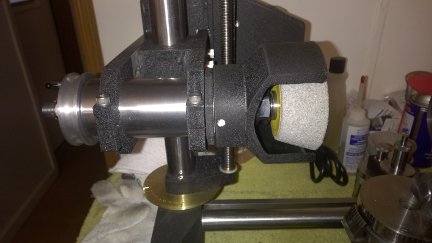
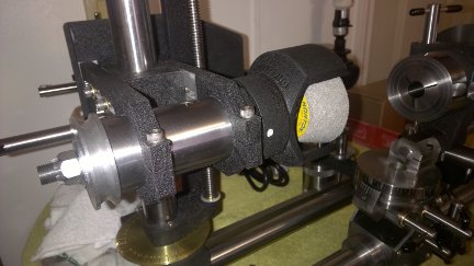
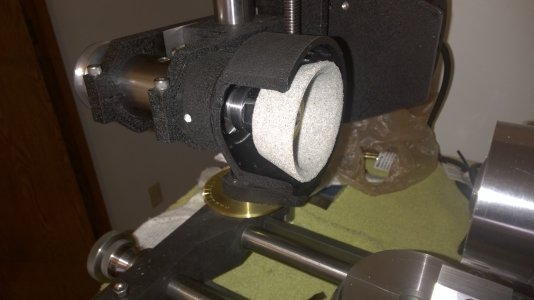
They are great. This one is for the 3 inch wheel and there is another for the 4 inch wheel. They cost a total of $8 for the pair. They are practically indestructible, 1/4 inch thick PVC ( can't hardly break it with a hammer ) , it will certainly contain a wheel breaking up. And if you haven't figured it out , they are plumbing fittings!
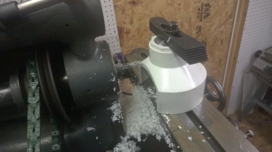 They are a 3 inch reducer with a 1 1/2" bushing bored to fit the spindle, then the opening is milled in the front as you see here. I drilled three holes tapped for 1/4-20 set screws to hold it on the spindle. Painted with the black wrinkle finish to match the machine.
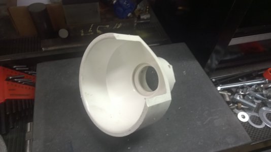
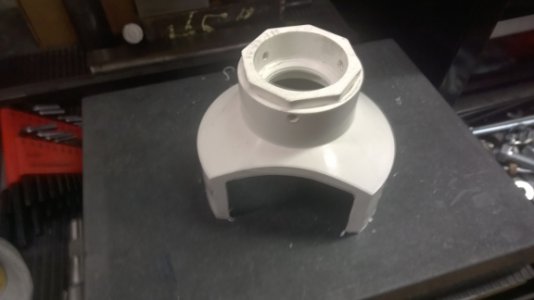 I was impressed with them. They are sturdy and simple.
Now I need to order a drive belt and make the drive pulley. It is getting really close now. I'm trying to find the material for the belt now.
I know the first thing I am going to grind is a couple of lathe tools...... threading tool and cutting tool, But that is still a little way off.
I have been thinking about wheel guards. They really should be installed ( but when doing your own build like this you can get away without them. They sure are nice if a wheel comes apart though. All the plans I have show some complex guards fabricated from steel and welded or soldered and look like a lot of work. I went to my local hardware store today and looked around for something to make them with...... And then I saw it .........wait for it.............TA-DA!!!!


They are great. This one is for the 3 inch wheel and there is another for the 4 inch wheel. They cost a total of $8 for the pair. They are practically indestructible, 1/4 inch thick PVC ( can't hardly break it with a hammer ) , it will certainly contain a wheel breaking up. And if you haven't figured it out , they are plumbing fittings!
 They are a 3 inch reducer with a 1 1/2" bushing bored to fit the spindle, then the opening is milled in the front as you see here. I drilled three holes tapped for 1/4-20 set screws to hold it on the spindle. Painted with the black wrinkle finish to match the machine.
 I was impressed with them. They are sturdy and simple.
Now I need to order a drive belt and make the drive pulley. It is getting really close now. I'm trying to find the material for the belt now.
I know the first thing I am going to grind is a couple of lathe tools...... threading tool and cutting tool, But that is still a little way off.
