-
Welcome back Guest! Did you know you can mentor other members here at H-M? If not, please check out our Relaunch of Hobby Machinist Mentoring Program!
You are using an out of date browser. It may not display this or other websites correctly.
You should upgrade or use an alternative browser.
You should upgrade or use an alternative browser.
Tool and cutter grinder build
- Thread starter Mark_f
- Start date
Man... the details take a lot of time. I spent half the day making the vernier "zero" marker for the rotary table base.
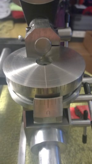 This is the finished marker installed. Yes, I made another mistake
  . I miscalculated the width needed and only got the 4 lines. No room for the fifth, but it is not needed anyway and with the hours in this one, I wasn't doing a "do-over" if I did not have to. The fourth line is right at the outside edge on each side. Amazingly it does work. This will ket you "eyeball" a pretty close setting, but if I had to be exact, I would use an indicator anyway.
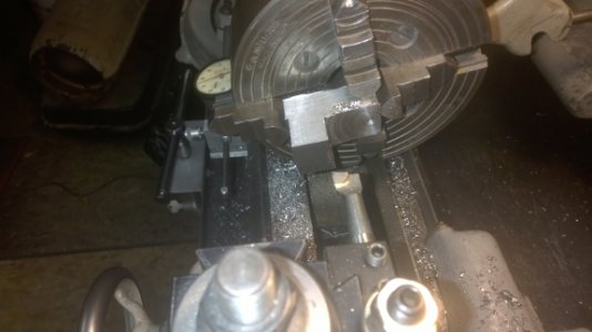 Here I am machining the radius for the vernier to fit around the arc of the table. There is probably some easier way to do this , but I work with what I got, so , I put a block of steel in the four jaw chuck and set it for 1/8" larger radius than the table and started whittling away at it.
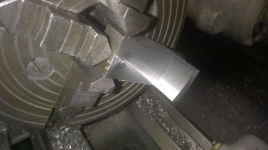 a few hours later, it is done (on the inside).
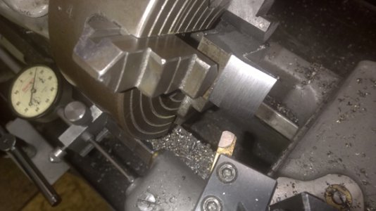 I used a radius-ed cutter to get a nice finish on the outside bevel. ( I used carbide just because I already had the cutter and didn't have to grind one.)
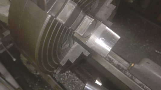 You can just see the end of the boring bar used to engrave the lines. At this point while it is set up it was best to go ahead and put the lines on. I put my degree wheel on the spindle and engraved a line every 4 degrees on both sides of zero. The fourth line is right at the outside edge of the cutter. I wished I had room for the fifth line but it is not needed anyway.
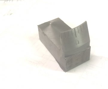 this is what it looks like right out of the lathe. I cut it to length in the band saw and then put it on the mill for finishing.
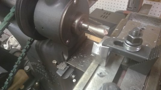 About an hour on the mill to cut the key on the back, clean up the sides, an angle the bottom and it is ready to mount on the grinder as seen in the first photo.
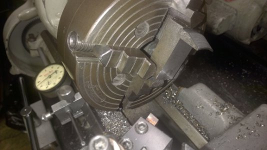
 This is the finished marker installed. Yes, I made another mistake
  . I miscalculated the width needed and only got the 4 lines. No room for the fifth, but it is not needed anyway and with the hours in this one, I wasn't doing a "do-over" if I did not have to. The fourth line is right at the outside edge on each side. Amazingly it does work. This will ket you "eyeball" a pretty close setting, but if I had to be exact, I would use an indicator anyway.
 Here I am machining the radius for the vernier to fit around the arc of the table. There is probably some easier way to do this , but I work with what I got, so , I put a block of steel in the four jaw chuck and set it for 1/8" larger radius than the table and started whittling away at it.
 a few hours later, it is done (on the inside).
 I used a radius-ed cutter to get a nice finish on the outside bevel. ( I used carbide just because I already had the cutter and didn't have to grind one.)
 You can just see the end of the boring bar used to engrave the lines. At this point while it is set up it was best to go ahead and put the lines on. I put my degree wheel on the spindle and engraved a line every 4 degrees on both sides of zero. The fourth line is right at the outside edge of the cutter. I wished I had room for the fifth line but it is not needed anyway.
 this is what it looks like right out of the lathe. I cut it to length in the band saw and then put it on the mill for finishing.
 About an hour on the mill to cut the key on the back, clean up the sides, an angle the bottom and it is ready to mount on the grinder as seen in the first photo.
would heat treating the bars stop some of the movement.
I doubt it. I am going to change the front micrometer bar to a piece of one inch drill rod and see if that makes a difference. The flexing movement is a collection of flex points from the sliding base on which sets the tilting base, on which sets the rotary table, on which sets the tool holder. the combination of all these parts stacked is going to give some flex. Actually , I am amazed it is as small an amount as it is.
My apologies, I got tied up in stuff at work (hate it when that happens...).
The solution Sir, is Moglice. I will use it for creating perfect bearing surfaces in the base pieces and the spindle. I've not personally used it but I did run across someone on the web building a Quorn or Bonnelle using it and had pics of his centering pieces for the bars and stuff. I will need to research detail stuff like ideal thicknesses of the material, setup, etc., but I'm fairly certain this will work. And it will be a whole lot easier than lapping and polishing with newspaper for weeks/months like the first time...
Bill,
I spoke with New Way air bearings today and they make a ready made air bushing and spindle material 1 1/2" diameter spindle and it runs close to $400. You install the bushing in your own mount with a specified bore and shove the air bearing ( has "o rings" on it) into your bore. hook up the air and you are done. I think you will find the Moglice pricey. Not as pricey as the bearing but you have to mess with it and center it and mix it and pour it. just not sure what the better route is without a price on moglice. Also , how slippery is the moglice? Still so many questions
B
Bill Gruby
Forum Guest
Register Today
Mark;
Forget about how much time it takes to get something done. It is irrelevant, that's how mistakes are made and the term, "That's good enough" comes into play. Neither are acceptable. It took me two days to get this pointer to look like I wanted it to. I made a total of seven of them before the one you see.
"Billy G"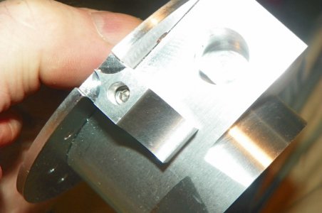

Last edited by a moderator:
Mark;
Forget about how much time it takes to get something done. It is irrelevant, that's how mistakes are made and the term, "That's good enough" comes into play. Neither are acceptable. It took me two days to get this pointer to look like I wanted it to. I made a total of seven of them before the one you see.
"Billy G" View attachment 97545
that is an excellent philosophy. I shall remember it.
I made the pointer and was undecided as to put the marks on it or make a brass adjustable scale to fasten to the steel pointer. I put the marks on to see how they look and work. I can always add the brass scale as it would cover the engraved lines. Right now , I am waiting to see if this arrangement grows on me.
Bill G.
I looked at the Quorn attachment ( for lack of a better word) for grinding flutes and it looks like they just made a longer spindle to go into the regular tool holder body Which on the Quorn appears to have a pinch lock setup. I would think it would not slide and turn easy enough, but I don't know.
I have only ever used an air bearing ( That was what they had where I once worked) and have been told a mechanical fit is too "sticky", but again, I don't know. I only know what I hear and I don't even know if that is even correct. The bottom line is "I don't know", but I would value your opinion on the subject.
B
Bill Gruby
Forum Guest
Register Today
Hang in there Mark. My tool holder will twist and ride on two rails with linear bearings. It will be adaptable to you machine. Trying to work on the Die Filer and get that done too is a big hassle.
"Billy G"
"Billy G"
B
Bill Gruby
Forum Guest
Register Today
I chose Linear Bearings with matched shafts. They are foolproof and keep everything moving in a straight line.
"Billy G"
"Billy G"
