The bino build came to a halt whilst I cleaned and tidied up the workshop, something that was long overdue.
In the course of tidying up I found my mirror tester covered in rat crap so took a short break to re furbish it even though I am no where near requiring it for testing as I havnt started grinding the mirrors yet but I just couldnt leave it in that appalling state.
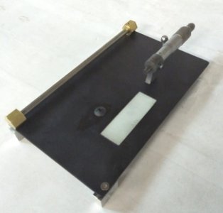
The micrometers had to be stripped and cleaned so I painted the base and added better slide supports and a fourth adjustable foot so it would sit in a stable position no matter what the surface.
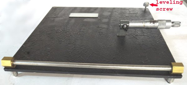
The long white rectangle is a glass microscope slide for the next stage to slide upon.
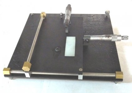
This is the second stage for the "X" direction and sits on the base like so. 2 "V" blocks slide on the stainless rail with the adjusting screw just to the left of the micrometer slides in the glass slide. Those little knurled thumb screws are the ones that filled my thumb with invisible splinters of stainless steel.
https://www.hobby-machinist.com/thr...earnt-something-new-lesson.76300/#post-639821
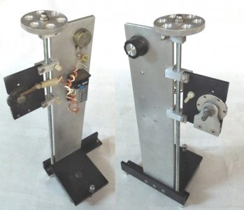
The "Y" and "Z" are a single unit on the third stage
and sits on the second stage.
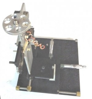
Both the second and third stage have lead blocks bolted to them as vibration dampers.
The sliding head is held with 2 nylon screws for friction and are locked when everything is in alignment.
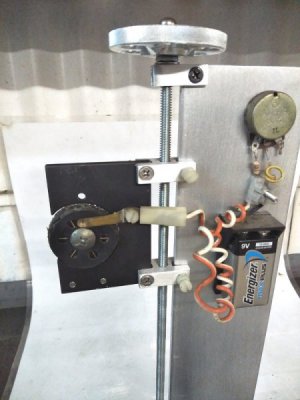
The wheel contains 6 diodes, red, green, blue, white, yellow and orange. No real reason as most testing will be done in green but I wanted to see if there was any difference in the readings with different colours,
The diodes are are switched on when they are directly below the peep hole.
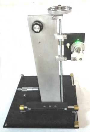
The rheostat controls the brightness of the diode.
I still have to attach the magnet that holds the screens or razor blade in place over the diodes as the rat crap ruined them.
Now I need some dry days to do a bit of casting and continue with the real job.
