Starting cap

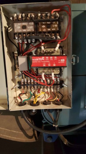
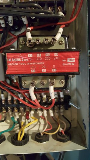
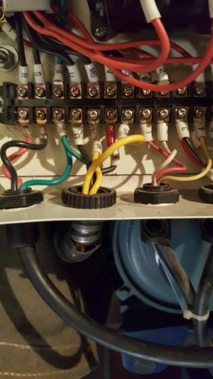
Will take a look tomorrow- till then... does the machine have a control box with contactors, transformer, etc.? Picture of that would be good also
Used to own a 1984 633csi, good freeway car
Had to let it go
everything in the box is wired right per a wiring diagram, I used to own a 1980 633csi got rid of it about 4 years ago but I still got my 650i best open highway car I have ever driven 135mph so far then the wife starts to get scared
 

Attachments

  • Photo 3.jpeg
    Photo 3.jpeg
    185.4 KB · Views: 6
  • Photo 4.jpeg
    Photo 4.jpeg
    200.2 KB · Views: 7
  • Photo 5.jpeg
    Photo 5.jpeg
    171.4 KB · Views: 7
  • Photo 6.jpeg
    Photo 6.jpeg
    128.5 KB · Views: 7
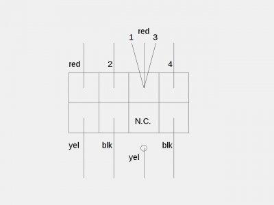
OK try this: Install your new cap. Disconnect the one yellow wire as shown and insulate the end with tape or heatshrink tubing.
Wire motor as per diagram.
Connect 240 volt power to R and S (leftmost terminals in control box; don't forget the ground wire)
If the rotation is backwards turn off power and swap the two red motor wires.

Edit: correct for phase swap as per the cover diagram in post #25
 

Attachments

  • 240v2ndconn.jpeg
    240v2ndconn.jpeg
    37.1 KB · Views: 1
Last edited:
OK let's try this: Install your new cap. Disconnect the one yellow wire as shown and insulate the end with tape or heatshrink tubing.
Wire motor as per diagram.
Connect 240 volt power to R and S (leftmost terminals in control box; don't forget the ground wire)
If the rotation is backwards turn off power and swap the two red motor wires.
If motor just hums or spins slowly we may have to backtrack and ohm out the motor wires 1 thru 4 to ID the windings
sorry, I forgot to give you that info, 1 and 2 are connected and 3 and 4 are connected 1.0 ohm on both, so your diagram is correct I assume
 
OK, should work then as drawn. There is a slight chance that they still might be out of phase but swapping 3 and 4 would remedy that
The factories sometimes do things backwards but fortunately not often
Edit: check drawing for update
 
Last edited:
OK, should work then as drawn. There is a slight chance that they still might be out of phase but swapping 3 and 4 would remedy that
The factories sometimes do things backwards but fortunately not often
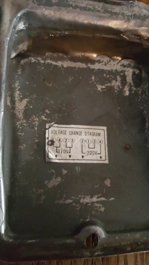
uh just found the motor wiring cover, i still dont understand this but i do understand your drawing
 

Attachments

  • Photo 2.jpeg
    Photo 2.jpeg
    158.7 KB · Views: 7
Aha! Those stinkers. You'll need to swap 1 and 2 (I'll correct the drawing)
The motor cover drawing shows the basic phasing connection to power for the 2 main windings
The start circuit isn't shown- not sure why.
With import stuff one has to expect goofy, incomplete data sometimes
 
Last edited:
Aha! Those stinkers. You'll need to swap 1 and 2 (I'll correct the drawing)
The motor cover drawing shows the basic phasing connection to power for the 2 main windings
The start circuit isn't shown- not sure why.
With import stuff one has to expect goofy, incomplete data sometimes
Bingo, that did the trick, Its spinning now thanks for all of your help I think Im gonna try and turn something now
 
Back
Top