Some Ideas for Ease of Use

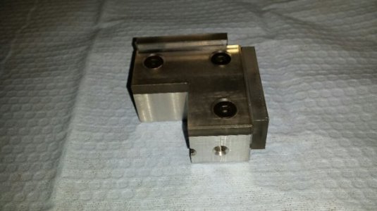
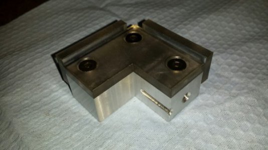
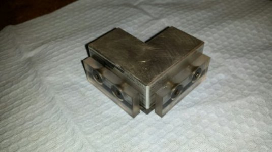
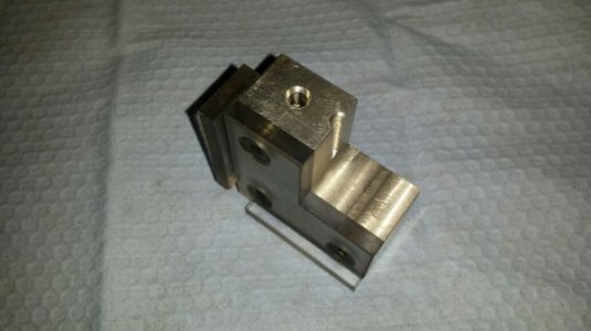
I'm pretty sure we're looking at the bottom. The inside metal corner edges are the 'known' X/Y surfaces, and the bottom and sides are plastic to insulate from the work piece. The metal plate is DC+, and the tool is DC- (perhaps through the spindle or another aligator clip. Flat head screws are recessed to maintain electrical insulation from part top surface. Damn clever.

Similar to my Z touch plates. Mine are spring-loaded so I can rapid down at 50IPM without chipping the tool (it does a second probe at about 4IPM). However, mine doesn't do X/Y - that's pretty cool. It's kind of like an inflexible spindle-mounted touch probe.

I don't see why you couldn't make a spring loaded probe that could do the same thing. Use a known diameter and you're in business. You could even make a spring-loaded button on the top instead of a telescoping probe thingie so you could do a two-pass fast-slow probe routine.

I'm still trying to figure out how to touch off quickly on oddball shaped things or the top of round parts without resorting to the old 'creep up on the scrap of paper' trick.

Your first paragraph is correct. I'll take more pictures and post them. DC- is through the spindle.

Tom S.
 
Your first paragraph is correct. I'll take more pictures and post them. DC- is through the spindle.

Tom S.

Here are more pictures of my X,Y,Z Zero setter. Hope this makes it a bit more clear on how it is used. I can provide the button script if you are interested.

Originally this was a Z setter only. It was 2" square and 1" thick including the insulation material. I machined the notch so each leg is 1" wide and added the plastic
ledges.
20170427_093336_resized (1).jpg

The groove in the right hand leg is the original hole I used to attach the DC+ wire.
20170427_093409_resized.jpg

Top view.
20170427_093425_resized.jpg

20170427_093515_resized.jpg
 
I think I see it better.

So you put that piece on the corner of a piece of stock you want to be your reference, plastic side down, and you know that when your ohmmeter goes to zero on each axis in succession, you're at (-1, -1,+1)?

Cool.
 
MontanaAardvark,

If it's like mine, and every other one I've seen on TV, the DC+ comes from an input pin on the breakout board to the tool setter plate. There's no ohmmeter; when it grounds through the tool & spindle the breakout board pin is driven high (or low? can't remember) and the controller sees the pin state change. When the probe routine is started, the macro/script moves the table and is continuously checking for a state change on that pin and registers the change. It then immediately writes the position to the DRO after compensating for the 1" offset and tool radius which was already entered in some screen field before the probing routine. After the DRO position is updated, the machine is commanded to move some distance off the setter (1-1/2" if I recall) and move to the Y-axis start position. Repeat, and do it again for Z.

The first time you see the probing routine do it's thing it's like magic: creep-touch, creep-touch, creep-touch - then zoom to origin with the Z at some conveniently safe height above the part.

That's why the probing routines are usually very slow and you need to jog pretty close to the start point before initiating the routine. You don't want to wait for it to creep at 4IPM when your table is over in the next county. It's done slowly - especially in this particular case when there's a rigid tool about to contact a rigid(ish) tool setter - because if you go fast the machine still has to decelerate after the pin state change and those few 'thou can ding something. It's also why I mentioned a spring-loaded probe or plate, because then you could zoom over to the setter and bang in to it at speed and nothing's bent. Of course, the macro then does it again at slow speed to get a very precise reading, but that time the macro just backs off 0.025" from the first contact location for the second (final, accurate) probe.

The upside to this compared to a regular touch-probe is that there are no internal contacts to corrode like on a low-end probe. You don't have to worry about the probe stylus being bent from your last crash, or the internal contacts tripping at different distances based on orientation in the spindle and angle of approach. It's also free, more or less - just some wire and a few bits of scrap laying around.

The downsides, and they aren't bad, are that this arrangement needs the part to have a square corner and be held in a trammed vise (or trammed to the table). Also needs a flat top for the Z to work, or at least a flat surface adjacent to the corner. Finally, I wouldn't trust some of my cheap drill bits to have low enough run-out at the tips to trigger the touch plate within 0.01" of the true spindle position. A 4-flute end mill or stubby carbide drill - yes. Most of my drill bits or a 2-flute end mill with big gullets - no way.

I'm also betting that Mr. Clever here (TomS) has come up with some workarounds to address the downsides I've been speculating about.

-S

Sorry - retired electrical engineer so to me, it's kind of an ohmmeter. When I get in a hurry, I write what's dumping out my head.

I'm familiar with how it works and was looking at how to implement it on my mill and the controller box I built.

On the other subject, I was looking at this starter set of TTS holders, but realized the drill chuck holder is the wrong size for my chuck, which is JT33. They make one, it's just not in the set.


Bob
 
I think I see it better.

So you put that piece on the corner of a piece of stock you want to be your reference, plastic side down, and you know that when your ohmmeter goes to zero on each axis in succession, you're at (-1, -1,+1)?

Cool.

In essence, yes. The script can be modified to put the tool where you want it. My current button script language moves the tool 1-1/2" in X and Y and resets the DRO to zero. In Z it moves 1" and sets the DRO to +1". I found the VB script on the internet. I'm not that familiar with script language so haven't tried changing the language so X and Y work like Z. Still it works great.

Tom S.
 
MontanaAardvark,

If it's like mine, and every other one I've seen on TV, the DC+ comes from an input pin on the breakout board to the tool setter plate. There's no ohmmeter; when it grounds through the tool & spindle the breakout board pin is driven high (or low? can't remember) and the controller sees the pin state change. When the probe routine is started, the macro/script moves the table and is continuously checking for a state change on that pin and registers the change. It then immediately writes the position to the DRO after compensating for the 1" offset and tool radius which was already entered in some screen field before the probing routine. After the DRO position is updated, the machine is commanded to move some distance off the setter (1-1/2" if I recall) and move to the Y-axis start position. Repeat, and do it again for Z.

The first time you see the probing routine do it's thing it's like magic: creep-touch, creep-touch, creep-touch - then zoom to origin with the Z at some conveniently safe height above the part.

That's why the probing routines are usually very slow and you need to jog pretty close to the start point before initiating the routine. You don't want to wait for it to creep at 4IPM when your table is over in the next county. It's done slowly - especially in this particular case when there's a rigid tool about to contact a rigid(ish) tool setter - because if you go fast the machine still has to decelerate after the pin state change and those few 'thou can ding something. It's also why I mentioned a spring-loaded probe or plate, because then you could zoom over to the setter and bang in to it at speed and nothing's bent. Of course, the macro then does it again at slow speed to get a very precise reading, but that time the macro just backs off 0.025" from the first contact location for the second (final, accurate) probe.

The upside to this compared to a regular touch-probe is that there are no internal contacts to corrode like on a low-end probe. You don't have to worry about the probe stylus being bent from your last crash, or the internal contacts tripping at different distances based on orientation in the spindle and angle of approach. It's also free, more or less - just some wire and a few bits of scrap laying around.

The downsides, and they aren't bad, are that this arrangement needs the part to have a square corner and be held in a trammed vise (or trammed to the table). Also needs a flat top for the Z to work, or at least a flat surface adjacent to the corner. Finally, I wouldn't trust some of my cheap drill bits to have low enough run-out at the tips to trigger the touch plate within 0.01" of the true spindle position. A 4-flute end mill or stubby carbide drill - yes. Most of my drill bits or a 2-flute end mill with big gullets - no way.

I'm also betting that Mr. Clever here (TomS) has come up with some workarounds to address the downsides I've been speculating about.

-S

You got it! I use a 3/8" dowel pin in a dedicated holder to touch off X and Y. Then use the cutter/end mill for the job I'm running to set Z. I jog the table until my "probe" is about 1/2" from the touch off surfaces then run the routine.

It does have it's limitations but for setting up square or rectangular stock it works. And, as you said, it cost me nothing to make.

Tom S.
 
If you want to try out the TTS, for similar money you can get this ER20 collet set.

They also have ER11, 16, 25, and 32 available. Can also get them with the TTS ATC groove for a bit more money. They aren't all listed on the ebay site, so send them an email - they responded to me within 8 hours. Shipping is a little steep but it's FAST. I'm very, very pleased with the quality.

Then pick up a JT33 drill arbor and maybe one of the 0-1/4" chuck &arbor combos from Little Machine Shop. Assuming you already have a 3/4" R8 collet, just grind the face down until it's flat so the TTS flanges bear against the spindle nose.

If you have a DTI or some other measuring tool with a standard shank, you can make a holder like I mentioned earlier in the thread or buy the dedicated set-screw holders a la carte.

Don't buy collet sets, just buy the sizes you need. I noticed after buying a couple of sets I really only use 1/2, 3/8, 1/4, 3/16, and 1/8. All the xx/64ths and 32nds are a waste.

Being an electrical engineer I can't imagine you'd need much help, but if you want some help with the probe wiring just let me know what BOB you have and if you're running Mach3 or what.

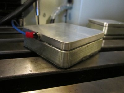
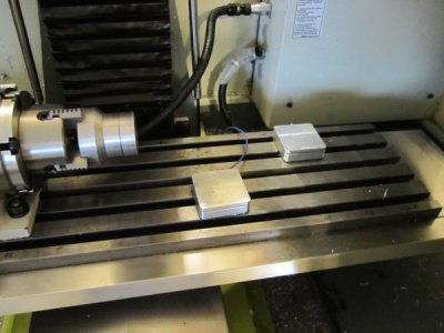
Photo of my plates below. Front plate is put on top of the part, and back plate is stationed at machine 0, 0. Jog over the moveable plate, hit the tool-zero initiate and it goes down at 50IPM and touches off. Repeat at 4IPM after a 0.025" backoff and it writes part Z 0 based on the thickness of the plate. It then moves to machine 0, 0 and does the same thing on the stationary plate and writes the difference between Z0 and the stationary plate to a register in the controller. Moveable plate is removed from part and you start machining (after setting X/Y off-sets). All tool changes in the program after the initial probe routine are touched off the stationary plate. The code pauses at M6, you switch tools and tell it go - it then probes, sets the new Z height based on the difference between the two plates, and gets on with machining.

And with this setup you don't need TTS, because your tool offset is always 0. The Z off-set is changed, but there's no tool off-set applied so you can use regular R8 collets that don't repeat when you swap them out. I just prefer to use TTS because if's fast and I want to build an ATC eventually.

Closest thing to an ATC I've ever seen. If you're running Mach3, Google & buy the "2010 Screenset" and make yourself some touch plates. The screenset is stupid cheap for all the features and you're not dependent on everything being TTS before you start using it.
IMG_3400.JPG IMG_3399.JPG IMG_3396.JPG
 
If you want to try out the TTS, for similar money you can get this ER20 collet set.

On my end, when I click on that I get a Little Machine Shop page for their 33JT to TTS adapter. It's supposed to be someone on eBay?

I was just pricing a "starter set" of TTS parts (not the starter kit Tormach sells) and I'm at $295 with a small ER-32 collet set and a few other holders. I need to seriously look at limiting the number of cutters I have, or that description of how to make some. I have a couple of 3/4" shaft cutters I want to use: a face cutter and an end mill. It looks like I'd need two TTS ER-32 collet holders and two 3/4" collets.


Bob
 
Crap. I suck at posting links. Try this one.

For your 3/4" shank cutters you could just make a flange that registers against the spindle nose and stick the shank straight in the TTS spindle collet. If the end mill is too short for that, you'll need an ER32 as you mentioned.
 
Back
Top